Finally starting my build \o/
An externally hosted image should be here but it was not working when we last tested it.
BoM error
I seem to have found an error in the BoM, the 6x 220uF 50v caps are listed as 647-UKZ1E221MHM in the BoM these are actually only 25v.
BoM:
(6)220UF/50V C3 C4 C8 C9 C10 C28 220UF/50V 647-UKZ1E221MHM
Mark.
I seem to have found an error in the BoM, the 6x 220uF 50v caps are listed as 647-UKZ1E221MHM in the BoM these are actually only 25v.
BoM:
(6)220UF/50V C3 C4 C8 C9 C10 C28 220UF/50V 647-UKZ1E221MHM
Mark.
I wish I had known. I ordered one pcb as soon as it became available but it still in the mail. It reappears in Chicago after a few days for the third time now....Promitheus, I have a few (3) white (pink ones are gone} PCBs available in Germany. If you are interested, PM me.
Cheers, Ernst
I wish I had known. I ordered one pcb as soon as it became available but it still in the mail. It reappears in Chicago after a few days for the third time now....
Pitty, I am sorry. Since the Gerbers were available I've ordered them - just a few days before the store made it available and thought there might be some interest here in Europe. 3 are not enough 🙂
Cheers
Ernst
Thanks for notifying us... anyways, since the psu-voltage in my Whammy will be +/- 17 Vdc all electrolytics will be 35V. The ones in the PSU hardly allow anything bigger than 3300uF/35V.I seem to have found an error in the BoM, the 6x 220uF 50v caps are listed as 647-UKZ1E221MHM in the BoM these are actually only 25v.
BoM:
(6)220UF/50V C3 C4 C8 C9 C10 C28 220UF/50V 647-UKZ1E221MHM
Mark.
One question about the gate-resistors, preventing oscillations: They currently are 499 ohms (1%), but how much margin do these resitors allow and what will be the audible effects?
Hi everyone, is there a way to modify the gerber file in order to put 2 circuits on a single pcb for a balanced version, and to change the size of some components and eliminate the power supply from the pcb itself to make it separate?
Hi everyone, is there a way to modify the gerber file in order to put 2 circuits on a single pcb for a balanced version, and to change the size of some components and eliminate the power supply from the pcb itself to make it separate?
This would be interesting if you can do it but you will need to ask Wayne for the original Eagle .brd and schematic files.
That would be nice but I doubt Mr. Wayne would do this. Another option would be to redesign the circuit. But I do not want to maybe 🤣
Thanks for notifying us... anyways, since the psu-voltage in my Whammy will be +/- 17 Vdc all electrolytics will be 35V. The ones in the PSU hardly allow anything bigger than 3300uF/35V.
One question about the gate-resistors, preventing oscillations: They currently are 499 ohms (1%), but how much margin do these resitors allow and what will be the audible effects?
The 220 uF 50 Volt could all be 25 Volt parts the 50V are in stock here. The gate resistors could be from 100-1000 Ohms and be fine I am doubtful it would be audible.
Wayne, thanks for the helpful answer 😉The 220 uF 50 Volt could all be 25 Volt parts the 50V are in stock here. The gate resistors could be from 100-1000 Ohms and be fine I am doubtful it would be audible.
I'm not very accustomed to the use of FET's, more BJT's, so that's why I'm asking.
Will do, I have an email into Dennis @ Burson which will hopefully get answered by Monday.Interested to finding out if the Bursons work. Keep us posted.
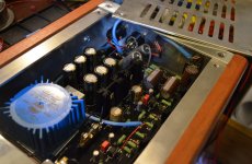
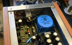
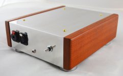
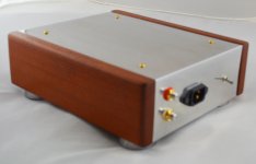
Have a few more pics attached. Chassis is from my friend Horace at IAG DIY Tube Audio Products. You can find his chassis selection at http://stores.ebay.com/iagdiytubeaudioproducts/
...I've been using his chassis for many years. Great product, hand-made in the USA.
The front panel has a four pin as most of my headphones are wired that way, so it saves me from using an adapter.
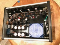
Wiring is scraps of Cardas I had in my wire bin, 4x24, 2x24 and 2x21 and some 24AWG. Pot is Audionote. IEC filter is Furutech, picked a few up when they were discontinued for a nice price. RCAs are Cardas. Most of the caps in the audio section are SILMIC II. I know Wayne mentioned in the video they aren't as reliable lately, but they sound good... so hopefully they'll be okay for a while. Resistors are mostly Koa Speers 2W with some Vishays here and there. Input coupling are vintage 100V Sprague PIOs. PSU caps are Nichicon "For Audio"... for whatever that's good for 😉 Everything else is from the BOM. If you use the same parts you should end up with a warmer sounding amp... although the op-amp will probably make more difference than all those other items.
Attachments
-
 WHAMMY internal front headphone amp.jpg666.1 KB · Views: 2,104
 -
 WHAMMY internal rear headphone amp.jpg605.4 KB · Views: 2,094
 -
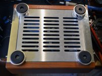 WHAMMY bottom DIY headphone amp.jpg858.1 KB · Views: 1,930
 -
 WHAMMY DIY front headphone amp.jpg563.2 KB · Views: 1,861
 -
 WHAMMY DIY rear headphone amp.jpg436.8 KB · Views: 1,862
Last edited:
I guess it's too late to edit the last message, but for the LED on the front, just in case anyone needs one, I ran off the 22V AC secondary and used a couple of spare parts to rectify/protect the LED. D1 can be any of the 1N400X series ... I happened to have a UF4004 laying around. There's probably easier ways of doing this but I'm used to tube amps where I just pull the AC off one of the heaters. The schematic is modified from a Classic Valve design.
Attachments
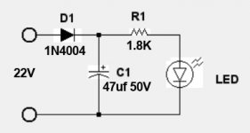

At that resistor value, the LED must be almost blinding....😀I guess it's too late to edit the last message, but for the LED on the front, just in case anyone needs one, I ran off the 22V AC secondary and used a couple of spare parts to rectify/protect the LED. D1 can be any of the 1N400X series ... I happened to have a UF4004 laying around. There's probably easier ways of doing this but I'm used to tube amps where I just pull the AC off one of the heaters. The schematic is modified from a Classic Valve design.
Without any bright tubes on top I like to know it’s on 😉At that resistor value, the LED must be almost blinding....😀
Will do, I have an email into Dennis @ Burson which will hopefully get answered by Monday.
Have a few more pics attached. Chassis is from my friend Horace at IAG DIY Tube Audio Products. You can find his chassis selection at http://stores.ebay.com/iagdiytubeaudioproducts/
...I've been using his chassis for many years. Great product, hand-made in the USA.
The front panel has a four pin as most of my headphones are wired that way, so it saves me from using an adapter.
Wiring is scraps of Cardas I had in my wire bin, 4x24, 2x24 and 2x21 and some 24AWG. Pot is Audionote. IEC filter is Furutech, picked a few up when they were discontinued for a nice price. RCAs are Cardas. Most of the caps in the audio section are SILMIC II. I know Wayne mentioned in the video they aren't as reliable lately, but they sound good... so hopefully they'll be okay for a while. Resistors are mostly Koa Speers 2W with some Vishays here and there. Input coupling are vintage 100V Sprague PIOs. PSU caps are Nichicon "For Audio"... for whatever that's good for 😉 Everything else is from the BOM. If you use the same parts you should end up with a warmer sounding amp... although the op-amp will probably make more difference than all those other items.
Beautiful and thanks for sharing the components used, it helps a lot
I used CAT5 wire for the hookup wire...
Any strong feelings towards its use? I figure solid copper can't be that bad, at such small runs.
Also used a Pansonic 0.1µF Film Capacitor 250V Polyester, Metallized Radial between the
chasis ground point and the input RCAs... just a part i had used in other power supply
Digi-key # ECQ-U2A104MV
Any strong feelings towards its use? I figure solid copper can't be that bad, at such small runs.
Also used a Pansonic 0.1µF Film Capacitor 250V Polyester, Metallized Radial between the
chasis ground point and the input RCAs... just a part i had used in other power supply
Digi-key # ECQ-U2A104MV
- Home
- Amplifiers
- Pass Labs
- "WHAMMY" Pass DIY headphone amp guide