Thanks 6L6 for the answer. I fully agree!!!...Use the parts in the kit, it's all good stuff. Instead of trying to make some incredibly small difference with passive part choices, make a real modification and 1) add input selection to turn it into a preamp, 2) have a switched output to choose headphone jack or RCA, and, if you are absolutely dying to try different parts, 3) try different opamps, because that will actually make a difference.
I did not buy replacements for the passive parts (other than the metallic green caps
).The ones I purchased were the more 'active' ones.
So, since I already have them, I'd still be interested in knowing if some of my 'replacements' would be better for this particular application.
Here's my choices:
- Kit's IRF610 - IRF9610 or ON Semiconductor's FQP3P20 - FQP3N30
- Kit's Optocuplers 4N35 (no idea what brand) or Vishay 4N35
- Kit's 7915 and 7815 voltage regulators or ON Semiconductor MC7815CTG and MC7915CTG
And, for the OpAmps, those are easier to try one or the other since they are not soldered in, but still would be nice to know what to expect (specially if some require less voltage or C2 and C7 oscillation controlling caps)
- Kit's Texas Instruments RC4580
- Texas Instruments LM833N/NOPB
- Texas Instruments OPA2134PA
- Analog Devices Inc. AD823ANZ
- ON Semiconductor LM833NG
Also, yes, I will add an RCA back output to use as a regular PRE. On this I will ask later if there is something special to take into account or if this is just the same outputs routed to the back. I'm still undecided if going for a switched 1/4" front connector or not. I bought the large Neutrik that has a secure latch, but it is so hard to push that the whole amp will be moved in trying to unplug the connector. Something is wrong with that design!!!
I won't go for a multi input, as I have DACs that have that covered, and everything I have has a single analog output. Perhaps a front 3.5mm connector for external sources could be interesting, but nos sure I want to complicate things all that much!
So, this is it for now, thanks for any feedback! I'll surely bother you guys some more with a myriad of questions as things move along (included front switch and the best way to send 110v 'across' the Chassis without risk of affecting the audio section).
Thanks a lot! Best regards,
Rafa.
Hi lads.
I just bought the board and want to order the parts for the psu. I'm a bit tight for cash otherwise I would have bought the kit.
I see some people are saying the 15v or 18v transformer is a better way to go rather than the 22v because of the heat and also better flexibility with opamps.
Can someone please give me the model number of the toroidal. Thanks.
So I'm guessing the 6363 is the one to go with?Hi lads.
I just bought the board and want to order the parts for the psu. I'm a bit tight for cash otherwise I would have bought the kit.
I see some people are saying the 15v or 18v transformer is a better way to go rather than the 22v because of the heat and also better flexibility with opamps.
Can someone please give me the model number of the toroidal. Thanks.

I bought the L01-6363 from Digikey. Dont know how I missed that.
L01-6363 Amgis, LLC | Transformers | DigiKey
Anyone know where I can get these from or recommend a substitute? They are not in stock.
(2) .1UF C13, C23 .1uF 505-MKP2D031001FKA00
I ditched the Alps pot and will go with the spare Eizz 50k Stepped Pot I have.
Thanks for this great build. I cant wait to start building!
Here's my choices:
- Kit's IRF610 - IRF9610 or ON Semiconductor's FQP3P20 - FQP3N30
- Kit's Optocuplers 4N35 (no idea what brand) or Vishay 4N35
- Kit's 7915 and 7815 voltage regulators or ON Semiconductor MC7815CTG and MC7915CTG
I can't tell the difference between IRF or Fairchild mosfets. They both work and sound great.
Regulators and optocouplers are not going to make any difference.
And, for the OpAmps, those are easier to try one or the other since they are not soldered in, but still would be nice to know what to expect (specially if some require less voltage or C2 and C7 oscillation controlling caps)
- Kit's Texas Instruments RC4580
- Texas Instruments LM833N/NOPB
- Texas Instruments OPA2134PA
- Analog Devices Inc. AD823ANZ
- ON Semiconductor LM833NG
I've used all those with the LED reference PSU and no compensation caps. They work great!
(included front switch and the best way to send 110v 'across' the Chassis without risk of affecting the audio section).
I'd suggest using a couple of wires. Twist together as they hold AC.
``````````
Henryve - use the 470nf X cap, or leave it open.
I plan on using an opamp that shouldn't need it, but in the event I do, what is the lead spacing on the board for the compensation caps?
You don't want to recommend the overkill approach of a rotary switch mounted at the rear with an extension shaft all the way up front?I'd suggest using a couple of wires. Twist together as they hold AC.
Great, thanks. I just don't want to be stuck with a 5mm cap and 2.5mm or 7.5mm spacing and no way to get those stubby leads in there without jumpers and making a mess of it.
And I honestly never bother looking for 2 pos rotary switches, so I never really worry about it either. I'm still not sure if I'll bother trying to figure one out or not if I've already got a switched PEM.
And I honestly never bother looking for 2 pos rotary switches, so I never really worry about it either. I'm still not sure if I'll bother trying to figure one out or not if I've already got a switched PEM.
Well, incredible pricing for the Cyber Monday WHAMMY! $56 off for the parts + PCB kit!
It's so good I may actually purchase a second one!
EDIT! PLEASE READ: There may an error in the pricing, as the blog says its just going to be 10% off, not the 30% that is showing now... possibly because it is being treated as PCB instead of parts. Those not wanting to take advantage of the DIY Audio Store, be aware there may be an error, don't just jump on the opportunity to take advantage of them. You have here a heads-up!
Last edited:
I just bought all the gear only 3 days ago. [emoji24][emoji24][emoji24][emoji24][emoji24][emoji24][emoji24][emoji24][emoji24][emoji24][emoji24][emoji24][emoji24][emoji24][emoji24][emoji24]
I still have to buy all the bits for the Honey Badger, Aleph Mini and Mezmerize Pre Amp lol.
I still have to buy all the bits for the Honey Badger, Aleph Mini and Mezmerize Pre Amp lol.
I did the same... but I'm not overly sad: I get to make mine before Christmas... these are to be sent in January.
Also, as I edited my post above: There may an error in the pricing, as the blog says its just going to be 10% off, not the 30% that is showing now... possibly because it is being treated as PCB instead of parts. Those not wanting to take advantage of the DIY Audio Store, be aware there may be an error, don't just jump on the opportunity to take advantage of them. You have here a heads-up!
Also, as I edited my post above: There may an error in the pricing, as the blog says its just going to be 10% off, not the 30% that is showing now... possibly because it is being treated as PCB instead of parts. Those not wanting to take advantage of the DIY Audio Store, be aware there may be an error, don't just jump on the opportunity to take advantage of them. You have here a heads-up!
Well, I think I'm ready to decide upon a case distribution and wanted your always enlightened advice!
Since I'll be matching my WHAMMY with my ACA, the width of my case is a bit wider than most cases showcased here. That gives me a little freeway in terms of placement.
I have narrowed it down to these 3 options:
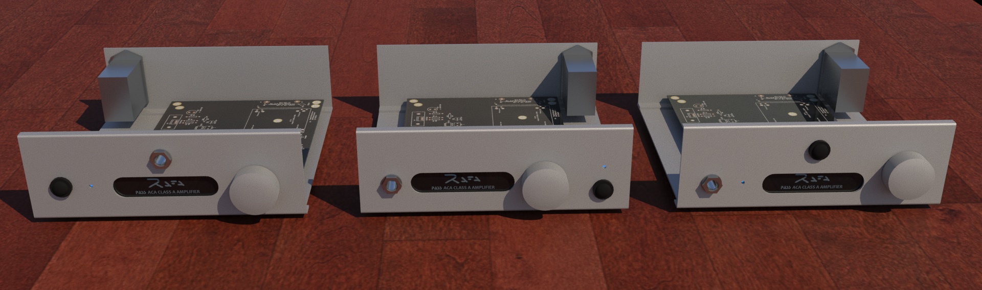
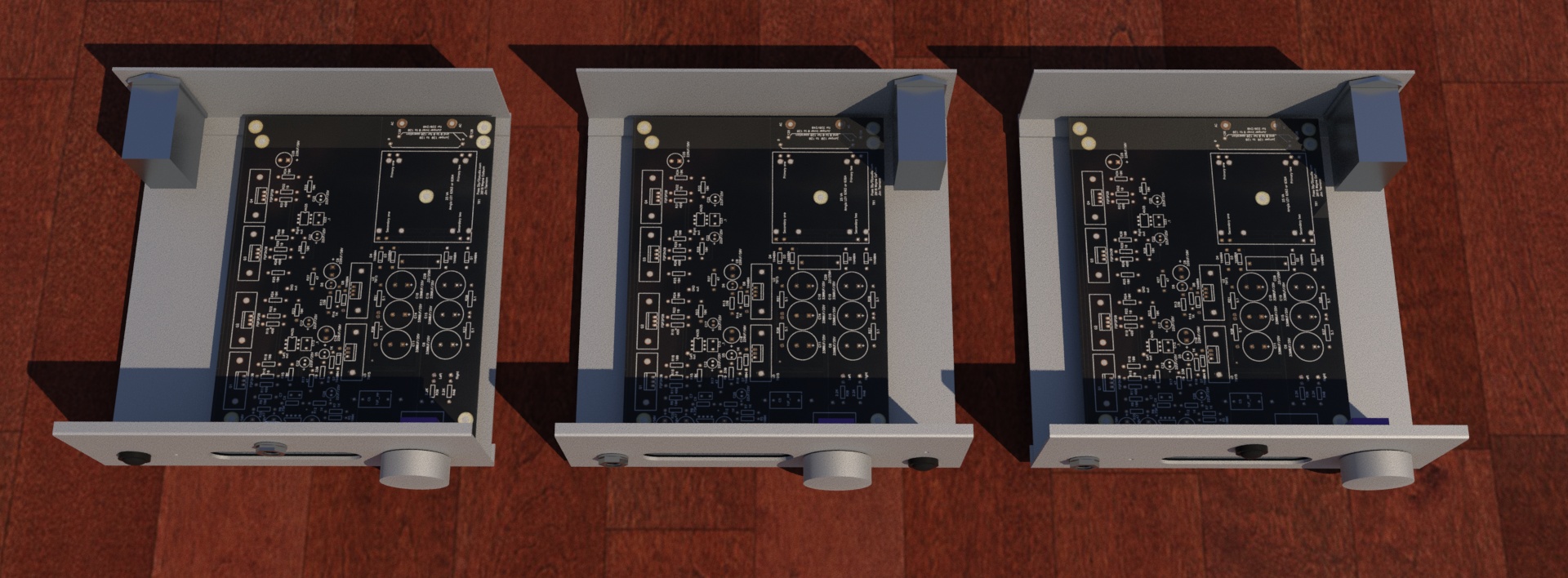
Lets call them A, B, C from left to right.
The 'simplest' and 'cleaner' approach is B:
So... this evolved into A:
My final and preferred look and approach is C:
So, my questions at this point are:
As usual, thanks for any feedback, suggestions, critique, etc.! I really appreciate it.
I have decided to go with a switched headphone jack to create the WHAMMY as a PRE also, so I'm eagerly reading other's approach at this as well.
Thanks Wayne for a beautiful project and 6L6 for an incredible guide. Really looking forward to this project.
Best regards,
Rafa.
Since I'll be matching my WHAMMY with my ACA, the width of my case is a bit wider than most cases showcased here. That gives me a little freeway in terms of placement.
I have narrowed it down to these 3 options:
Lets call them A, B, C from left to right.
The 'simplest' and 'cleaner' approach is B:
- It has the Power connector right next to the Transformer
- It leaves all the 'power polluting' items (including front switch - rendered as a black blob -) on the right hand side of the case
- Has the Pot mounted ON the PCB (more on this later)
- Has the poorest aesthetic value
So... this evolved into A:
- It has better aesthetic balance...
- ... but sacrifices the cleanness and gets the power input near the 'audio' side. Still off the PCB (the front power switch will reside on the far left of the case)
- What bothers me is that the power cables will cross beneath the RCA inputs and through the back of the PCB into the AC connectors on the other side
- Still, not the best looking option
- Worst thing is the headphone jack on middle-top... really un-intuitive placement
My final and preferred look and approach is C:
- It keeps the power input next to the transformer
- It looks balanced and every connector and knob is where it should be
- It has a CENTER front power switch. This involves a cable from back-right to front-center (this sounds like ballet directions! ) carrying 110V!!! to the front AND back
- To complicate things, this options has the Pot mounted to the front plate and NOT to the PCB. I will need to connect the pot to the PCB with cables, possible degrading the audio signal.
So, my questions at this point are:
- Is there rason to be concerned about the 110V going fron the back to the front and back again through the middle of the case? Or will this not affect much the sound?
- How much of a sound degradation (if any) is there in taking the pot off the PCB? What has to be done to prevent problems?
- What am I NOT seeing that you think may be an issue when building these options?
As usual, thanks for any feedback, suggestions, critique, etc.! I really appreciate it.
I have decided to go with a switched headphone jack to create the WHAMMY as a PRE also, so I'm eagerly reading other's approach at this as well.
Thanks Wayne for a beautiful project and 6L6 for an incredible guide. Really looking forward to this project.
Best regards,
Rafa.
Attachments

Last edited:
- Home
- Amplifiers
- Pass Labs
- "WHAMMY" Pass DIY headphone amp guide