I have been surprisingly happy with the V5i in spite of my mistakes with it. It is a little forward sounding for my taste, yet with certain cans it is a win. So far I have tried the Hi-Fi Man400se and really like what it does with the bass for these cans. Then I tried the Beyer Dynamic DT770 pro which already has great bass and found it to be too much in every dept. The DT are more sensitive too. Never having been one to stand in one place for long, I am now working on the DT770 pro which involves adding detachable cables, and some 'special' padding for the inside of the cups. No idea of how it will turn out yet, as the new cable has just been ordered (Mogami 2592?), but the parts involved for the rest of this cable upgrade are really good. Got the plug from another guy on this site, and it is the best one that I have seen for aftermarket. More later, less sooner.

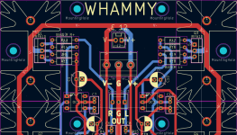
Can't tell from photo, but are you using an opto coupler here? It doesn't look like it.Another whammy coming right up. Looks like i did not mess up the measurements.
View attachment 1468800
Its under the E12.It doesn't look like it.
Attachments
Whammy is up and running, kinda. Waiting for the arduino nanos to be delivered so i can re-flash the R2R volume controller and do some cable management.
Not the most beautiful thing but it works for me. I used my spare muses8920 till the opa1656 arrives. DC offset on the right channel is 1-2mV and cannot measure the right one as it shows 0. Went with the basic gain config with no compensation caps and 20 ohm bias resistors. The positive mosfet gets a bit warmer as i used 4.7K instead of 10k but the optocoupler takes care of it.
As for initial listening experience the highs are back and bass is there more but only a tiny bit better. For context my current dac developed some bass distortion but a new one is coming.
I ordered a set of M3 screws and nuts but it never arrived so i had to improvise.

As for initial listening experience the highs are back and bass is there more but only a tiny bit better. For context my current dac developed some bass distortion but a new one is coming.
I ordered a set of M3 screws and nuts but it never arrived so i had to improvise.
Its like the law of the universe that it works the day i build it but never after i screw the case together. Today i went to turn on the amp and no sound at all, the protection board never left protection. I measured the dc offset and it was oscilalting between +- 800mV on both channels. So i replaced the opamp with a NE5532, TL072 and LME49720 and the issue still presisted. I did every thing i could think of and as a last ditch effort i checked continuity between mains earth and power ground, yup 10ohm short.
The issue was right infront of me the whole time. The 1602 lcd displayed random garbage text rather than AMB Laboraties Lcduino VER... Opened up the psu and checked continuity between mains ground and power ground with the amp power cable disconnected and there it was. The cheap smps somehow shorted its ground to the mains ground overnight. Wrapped it up in tape and no more issues. The SMPS have its own metal enclosure.
The issue was right infront of me the whole time. The 1602 lcd displayed random garbage text rather than AMB Laboraties Lcduino VER... Opened up the psu and checked continuity between mains ground and power ground with the amp power cable disconnected and there it was. The cheap smps somehow shorted its ground to the mains ground overnight. Wrapped it up in tape and no more issues. The SMPS have its own metal enclosure.
If you don't want that, then you need to increase certain capacitors. I already wrote about it.
I honestly don't know what the hell is happening. My opa1656 arrived and i switched to it and that is when the shitshow started. I removed the DC caps and rolled the opa1656. Started up the amp, dc offset was 4.5mV and 1.8mV and it played music perfectly fine but the noise floor, dynamic range, THD, IMD, crosstalk worsened by a lot compared to muses. So i soldered 68pF comp caps and it improved drastically BUT with a massive caveat(forgot to save rmaa result). Now for the caveat, when i plugged in my heaphones there was only noise that did not change at all. So i added 100ohm+100nf to the input of the buffer board but nothing, added 10ohm+100nf zobel to the output, nope no luck. Added 220uf DC caps and nothing. So i installed a plain ne5532 and it was DEAD silent. As a piece of mind reinstalled the 1656 and insane amounts of noise again. I plugged it into my old amp and not a single issue with noise. My whammy really doesn't like the 1656 from the looks of it.
After 3 hours of trying to troubleshoot the 1656 i gave up. Tried all three 1656 i had, tried every single compensation cap value i had, soldering different supply decouplig caps and the noise wouldn't go away. I even reverted the amp how it was the first time i plugged it in but still no luck.
In the end i plugged in the lme47920 and gonna keep it in. It have less than 1mV DC offset on both channels without DC caps, exact same performance as the opa1656 without the headache.
Well, I had the same problem with a 1656, mine is SOIC so I mounted it on an AliExpress adapter and put some pins in it and as soon as I inserted it, noise, low volume, distortion and just a mess. I've already got 100pF compensation caps in (C2 and C7 ?) because I was going to use the MUSES02. I thought my soldering had killed it but perhaps that's not the case, I didn't spend much time investigating.
Oscillations, nothing else. Those adapters make it worse. And maybe you killed it with heating.
Last edited:
Dont have a scope so i can only speculate and try fiddling with it in the dark. Created a faraday cage from alu foil for the 1656 connected to mains earth and the noise went down a lot but the oscillation remained. Its a ground loop between something as in rmaa i can see multiples of 50Hz spikes before protection kicks in. Dont see this loop with the 49720.The OPA1856 oscillates for sure as you have that behavior.
Gonna mess with it tomorrow when im fully rested.
I set aside 200eur for a USB scope 4x250MHz with a function generator. Best spent 200eur in my life. It's not as good as the desktop model, but it's very useful.
And after even more trial and error i concluded that the 1656 wont be stable without a new pcb, better routing and aluminium case so lme49720 it is.
- Home
- Amplifiers
- Pass Labs
- "WHAMMY" Pass DIY headphone amp guide