Mooly thank you again!
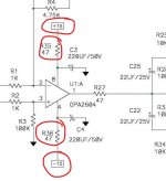
I placed black probe on Pin4 V- on Op Amp and red probe on resistor R37 and I confirm I read 16,34V on outer side of R35 and 16,20V on the inner one.
I also unmount the resistor to check that is value confirm to be 47,3 ohm.
Any other idea?
Thanks again!
I placed black probe on Pin4 V- on Op Amp and red probe on resistor R37 and I confirm I read 16,34V on outer side of R35 and 16,20V on the inner one.
I also unmount the resistor to check that is value confirm to be 47,3 ohm.
Any other idea?
Thanks again!
For voltage measurements you really need to be measuring from ground (use that as a reference and connect the black meter lead there). Ground is the zero volt line in the power supply.
Done that way and you should see negative 18v on pin 4 (which is what you mentioned) and positive 18v on pin 8.
So it looks like your positive 18 volt rail is missing from the power supply. Check those upper 5.1 ohm resistors are OK and not open circuit. Just measure the voltage on them, don't take them out. You should have 22v or higher on those.
Attachments
Lets start at the beginning ")
Your mains voltage will not make any difference as far as we are concerned.
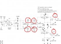
Look at the diagram here and if any component reference numbers are different then just make sure you are measuring on the correct points according to the circuit diagram.
Put your meter on DC volts and connect the black lead to the junction of C18/C19 and C14/C15. That line with that triangle symbol is our zero volt point. We measure from there...
R20 should have between positive 22 and positive 35 volts on both ends.
R37 should be similar.
R21 and R38 should be a mirror image, that is to say negative 22v to negative 35 volts on all the resistor legs.
If that is OK then check for positive 18v on the diode D7. One end will have the voltage you measured above whatever that might be, the other should be a steady positive 18 volts.
Now measure on D8. This again is a mirror image with negative voltages this time. So a steady negative 18v on one end of the diode.
Your mains voltage will not make any difference as far as we are concerned.
Look at the diagram here and if any component reference numbers are different then just make sure you are measuring on the correct points according to the circuit diagram.
Put your meter on DC volts and connect the black lead to the junction of C18/C19 and C14/C15. That line with that triangle symbol is our zero volt point. We measure from there...
R20 should have between positive 22 and positive 35 volts on both ends.
R37 should be similar.
R21 and R38 should be a mirror image, that is to say negative 22v to negative 35 volts on all the resistor legs.
If that is OK then check for positive 18v on the diode D7. One end will have the voltage you measured above whatever that might be, the other should be a steady positive 18 volts.
Now measure on D8. This again is a mirror image with negative voltages this time. So a steady negative 18v on one end of the diode.
Attachments
It is not D7 at fault Look at the circuit and try and follow this:
You need to check now (and be super careful not to short anything) that the positive 33 volts you have on R37 and on D7 is making it to pin 1 of the 7815 regulator.
You could also (with it OFF) check for continuity (using a low ohms range on the meter) from the resistor to pin 1.
I would guess that an open circuit is more likely than a fault at this point tbh. If you have soldered the regulator to a PCB then look carefully around the solder pads and make sure the pad has not lifted and cracked away from the print. A voltage check or continuity check will reveal that.
Look at the circuit and try and follow this:You need to check now (and be super careful not to short anything) that the positive 33 volts you have on R37 and on D7 is making it to pin 1 of the 7815 regulator.
You could also (with it OFF) check for continuity (using a low ohms range on the meter) from the resistor to pin 1.
I would guess that an open circuit is more likely than a fault at this point tbh. If you have soldered the regulator to a PCB then look carefully around the solder pads and make sure the pad has not lifted and cracked away from the print. A voltage check or continuity check will reveal that.

Need help with 4N35 orientation
I bought these optocouplers:
https://www.mouser.com/datasheet/2/427/4n35x-1767321.pdf
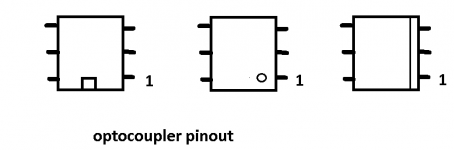
And they have no pinout marking or dot on them. There is a groove on one side. Any advice on how to install them?
I bought these optocouplers:
https://www.mouser.com/datasheet/2/427/4n35x-1767321.pdf
And they have no pinout marking or dot on them. There is a groove on one side. Any advice on how to install them?
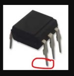
If they look like this then pin 1 is as shown.
Cool thanks.
That's strange isn't it! On the 'alldatasheet' page 7 (Vishay document 83717) the indent is clearly shown but on the one linked via the 'mouser' it shows a plain surface
You might be able to determine pins 1 & 2 using a multimeter/led tester - the resistance should show something like 100 -150ohms and the other pin on same side will show nothing = disconnected.
Perhaps someone else with first hand experience can be more helpful ...
You might be able to determine pins 1 & 2 using a multimeter/led tester - the resistance should show something like 100 -150ohms and the other pin on same side will show nothing = disconnected.
Perhaps someone else with first hand experience can be more helpful ...
Need troubleshooting help
I finished the build last evening and fired it up. The PS tested good previously. I'm getting no sound in the left channel and tinny sound in the right. Here are some voltages:
AD823 Opamp:
1 -.416v
2 0v
3 0v
4 -16.65v
5 0v
6 0v
7 -.43v
8 16.52v
Vishay 4N35-X006 Optocouplers
1 .495v
2 -.559v
3 0v
4 -.583v
5 5.32v
6 -.508v
Anything obvious here? This is my first amp fail after a number of builds.
- Home
- Amplifiers
- Pass Labs
- "WHAMMY" Pass DIY headphone amp guide