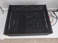
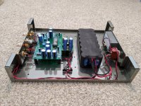
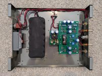
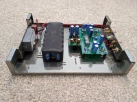
Well, it's pretty much done. I can't explain how many things went wrong, actually things are still going wrong. But it's working despite me manhandling it repeatedly (bent capacitors about a thousand times). Got boards all soldered up then realized I wanted wires routed underneath instead (think a speaker out pad is now threatening to lift). The Nutube is wildly microphonic... behaving worse with top case on chassis. Just problems galore. I still have to 3D print a battery tray and might need to add voltage divider.
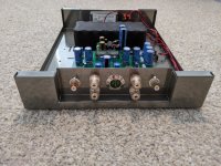
Certainly not an original idea. Dodd made a battery powered preamp. Altman had a battery powered amp and dac. Red Wine Audio made battery powered tubed HiFi. Mine is a battery powered hybrid amplifier via Korg Nutube B1 and Bottlehead Quicksand.
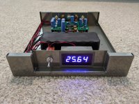
Not ready to report impressions yet. Waiting for battery to get closer to 24V to tune my tubiness. Not to mention my current source and speakers aren't ideal for critical listening. I'm hoping the charge circuit works, haven't tried that yet. The charge circuit and voltage display are separate from amp circuit. One switch position is amplifier on, one off, and one for voltage check or charging (assuming a charger is connected).
Certainly not an original idea. Dodd made a battery powered preamp. Altman had a battery powered amp and dac. Red Wine Audio made battery powered tubed HiFi. Mine is a battery powered hybrid amplifier via Korg Nutube B1 and Bottlehead Quicksand.
Not ready to report impressions yet. Waiting for battery to get closer to 24V to tune my tubiness. Not to mention my current source and speakers aren't ideal for critical listening. I'm hoping the charge circuit works, haven't tried that yet. The charge circuit and voltage display are separate from amp circuit. One switch position is amplifier on, one off, and one for voltage check or charging (assuming a charger is connected).
Attachments
-
 IMG_20200101_094322.jpg1,014.1 KB · Views: 587
 -
 IMG_20200101_094310.jpg996.1 KB · Views: 576
 -
 IMG_20200101_093540.jpg795.5 KB · Views: 565
 -
 IMG_20200101_093032.jpg876.8 KB · Views: 566
 -
 IMG_20200101_092949.jpg955.9 KB · Views: 555
 -
 IMG_20200101_092923.jpg1,010 KB · Views: 315
 -
 IMG_20200101_092804.jpg992.5 KB · Views: 305
 -
 IMG_20200101_092717.jpg1,008 KB · Views: 323
irishpatrick33
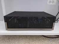
Beautiful build! I love the use of the ST-120 chassis. Is it a salvaged chassis or a clone? In any case, I hope you get the problems sorted out soon and can enjoy the wonderful music.
Beautiful build! I love the use of the ST-120 chassis. Is it a salvaged chassis or a clone? In any case, I hope you get the problems sorted out soon and can enjoy the wonderful music.
Is there any regulation of the battery voltage or how good will such a supply be to keep a stable voltage around 24VDC for at long time?
Looks like a nice stainless steel chassis.
Looks like a nice stainless steel chassis.
IrishPatrick33, nicely done! You could try buying a plastic cover from Japan for the Nutube so you can both display it but seal it from some outside noise. Though if you have access to a 3D printer you could make one too...
Well, it's pretty much done. I can't explain how many things went wrong, actually things are still going wrong. But it's working despite me manhandling it repeatedly (bent capacitors about a thousand times). Got boards all soldered up then realized I wanted wires routed underneath instead (think a speaker out pad is now threatening to lift). The Nutube is wildly microphonic... behaving worse with top case on chassis. Just problems galore. I still have to 3D print a battery tray and might need to add voltage divider.
Certainly not an original idea. Dodd made a battery powered preamp. Altman had a battery powered amp and dac. Red Wine Audio made battery powered tubed HiFi. Mine is a battery powered hybrid amplifier via Korg Nutube B1 and Bottlehead Quicksand.
Not ready to report impressions yet. Waiting for battery to get closer to 24V to tune my tubiness. Not to mention my current source and speakers aren't ideal for critical listening. I'm hoping the charge circuit works, haven't tried that yet. The charge circuit and voltage display are separate from amp circuit. One switch position is amplifier on, one off, and one for voltage check or charging (assuming a charger is connected).
Wow! Are you driving speakers directly from the preamp output? They must be very sensitive, what are they? What are you feeding the preamp with and how do you control volume?
Lovely job on the casework!
irishpatrick33
Beautiful build! I love the use of the ST-120 chassis. Is it a salvaged chassis or a clone? In any case, I hope you get the problems sorted out soon and can enjoy the wonderful music.
It's a new Dalaudio clone that I modified. The amp would have been done months ago if powder coaters weren't so uncooperative.
I built two chassis. I wasn't crazy about the powder job on first build, so I bought a second and powder coated it too. I kept the second chassis and now I am selling the first chassis, which is closer to chrome in color (on eBay and diyaudio marketplace).
Is there any regulation of the battery voltage or how good will such a supply be to keep a stable voltage around 24VDC for at long time?
Looks like a nice stainless steel chassis.
Wiser folks suggested that I shouldn't regulate (Thanks for the help, btw). It's a Nihm battery, so it should stay in the sweet spot (24V) longer than alkaline, I believe. Other than a whistling Nutube, it hasn't been misbehaving so far. Though it's been close to the target range, things could change around 29V or 20V.
So with one probe clamped on T5 I get these results probing the Nutube pins:
F1 = short
G1 = open
A1 = open
G = 12 ohm
F2 = 11 ohm
A2 = open
G2 = open
F3 = 22 ohm
Ground to Nutube G pin = short
Solder on caps looks good
F1 = short
G1 = open
A1 = open
G = 12 ohm
F2 = 11 ohm
A2 = open
G2 = open
F3 = 22 ohm
Ground to Nutube G pin = short
Solder on caps looks good
T6 to Nutube pins gets me this:
F1 = 23 ohm
G1 = open
A1 = open
G = 13 ohm
F2 = 12 ohm
A2 = open
G2 = open
F3 = short
F1 = 23 ohm
G1 = open
A1 = open
G = 13 ohm
F2 = 12 ohm
A2 = open
G2 = open
F3 = short
Hello Kevin 🙂
My are from T5 ( all rca and psu disconnected )
F1 = 0.2 ohm
G1 = 36.9K ohm
A1 = 331.9K ohm
G = 11.3 ohm
F2 = 11.4 ohm
A2 = 331.9K ohm
G2 = 36.9K ohm
F3 = 22 ohm
My are from T5 ( all rca and psu disconnected )
F1 = 0.2 ohm
G1 = 36.9K ohm
A1 = 331.9K ohm
G = 11.3 ohm
F2 = 11.4 ohm
A2 = 331.9K ohm
G2 = 36.9K ohm
F3 = 22 ohm
T6 to Nutube pins mesurement are :
F1 = 22 ohm
G1 = 36.9K ohm
A1 = 331.9K ohm
G = 11.4 ohm
F2 = 11.2 ohm
A2 = 331.9K ohm
G2 = 36.9K ohm
F3 = 0.17 ohm
F1 = 22 ohm
G1 = 36.9K ohm
A1 = 331.9K ohm
G = 11.4 ohm
F2 = 11.2 ohm
A2 = 331.9K ohm
G2 = 36.9K ohm
F3 = 0.17 ohm
Ok Kevin🙂
Listening music this evening with B1K and my caps is 2pairs of green Bipolar Nichicon MUSE with Silmic II at the outputs.
It's a wonderful little preamplifier. I stay in tune
Listening music this evening with B1K and my caps is 2pairs of green Bipolar Nichicon MUSE with Silmic II at the outputs.
It's a wonderful little preamplifier. I stay in tune
T5:
F1 = .4
G1 = 36.3
A1 = 333.3
G = 12
F2 = 12
A2 = 332.6
G2 = 36.3
F3 = 22.8
T6
F1 =24
G1 = 36.3
A1 = 333.3
G = 12
F2 = 12
A2 = 332.7
G2 = 36.3
F3 = .3
F1 = .4
G1 = 36.3
A1 = 333.3
G = 12
F2 = 12
A2 = 332.6
G2 = 36.3
F3 = 22.8
T6
F1 =24
G1 = 36.3
A1 = 333.3
G = 12
F2 = 12
A2 = 332.7
G2 = 36.3
F3 = .3
Last edited:
T5:
F1 = .4
G1 = 36.3
A1 = 333.3
G = 12
F2 = 12
A2 = 332.6
G2 = 36.3
F3 = 22.8
T6
F1 =24
G1 = 36.3
A1 = 333.3
G = 12
F2 = 12
A2 = 332.7
G2 = 36.3
F3 = .3
My are the same ~ 1% tolerance. So maybe solder joints of the capacitors or jfets ?
Let's move on from solder joints...they're all good. JFET's need to tested out of circuit, correct? I'm going to start clipping them out unless someone has a better idea.
Normally a solder suction pump can do the job. I like those with a soft tip of silicone (most has a hard teflon tip).JFET's need to tested out of circuit, correct? I'm going to start clipping them out unless someone has a better idea.
Litz wire can also be used to remove solder but can be more tricky with double layer PCB. I prefer a pump.
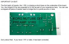
I powered up the board, the right side of the tube lights up blue, but the left side does nothing so I cut the power. Can I power back up and check voltages at test points?
View attachment 805815
I notice you have the revision 0 board. Did you remember to add the little solder bridge to the back of the board?
Attachments
- Home
- Amplifiers
- Pass Labs
- B1 with Korg Triode