For many purposes you can use all these parts - the 20+ Idss parts
operated at lower current figures, for example 7 to 10 mA, will give
comparable distortion performance in the buffers for crossovers and such.
Also, the high Idss parts are quite good as constant current sources -
they only require the appropriate Source resistance.
Nelson:
When establishing a J113 as a constant current source in the 7 to 10 mA range, is there a formula for determining the required source resistor value? Or do I need to set up a test rig with a variable resistor and adjust and measure for the desired result?
I bought several dozen J113s (total cost about 6 dollars) and have measured the Idss for them all using a Fluke meter accurate to within +/- 0.03 mA. They range from about 16 to 22 mA. It is fairly easy to match pairs within about 0.5 to 1.0 mA. Is matching pairs within 5% (1 mA for a 20 mA part) close enough?
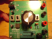
making Idss testing jig with 100R trimpot as source resistor is easier than typing your post.
no , ignore that ...... it's easier than typing this post
no , ignore that ..... in fact ignore everything ...... coffeemaker finished and off to first morning coffee

no , ignore that ...... it's easier than typing this post
no , ignore that ..... in fact ignore everything ...... coffeemaker finished and off to first morning coffee
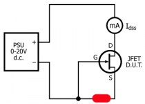
I often see this test rig for measuring Idss where PSU is 9V battery:
JFET Idss Matching – Stompville
When looking at the curves in datasheet Idss is a bit dependent of Vds. Idss raises a bit until the device breaks down…...and then it raises a lot. So when specifying a Idss you also need to specify a Vds?
Or is Idss defined at Vds just before break down?
For practical usage it probably doesn't matter...….if Idss is 7.9 or 8.2 mA.
in most cases range of Idss is what's important and not of much difference with Uds at say 9V and say 15V
but , matching ( as most important thing you going for) stays close enough
but , matching ( as most important thing you going for) stays close enough
If J177 was not marked as "obsolete" in TO-92 (seems it exists as smd) was this the "sister" to J113?
Will same happen to J113 so it could be a good idea to get some of then while they are cheap? …...and maybe J177 from another source if possible…..and then make test rigs to measure Idss.
Some sellers at ebay writes that they not only match Idss but also other parameters. Probably they play with Vgs and get some matching there also.
making Idss testing jig with 100R trimpot as source resistor is easier than typing your post.
no , ignore that ...... it's easier than typing this post
no , ignore that ..... in fact ignore everything ...... coffeemaker finished and off to first morning coffee
I personally ignored choosing the right profession when I was a bit, actually a lot, younger so I still don't understand electronics. Having said that so I have an apology to ask a stupid question: the source resistor is put here?
Attachments
Last edited:
When establishing a J113 as a constant current source in the 7 to 10 mA range, is there a formula for determining the required source resistor value?
There is, but it's just a lot easier to have a variable resistor on the Source.
I use a dip switch with 8 resistors with 0, 4.75, 10, 22.1, 47.5, 100, 221,
and 475 ohm values and a 12V supply.
Supply is not critical as long as it's consistent -you are only matching.
First I sort by Idss, with R=0, and put them in bins by 1 ma difference.
Alternatively you can do the first sort by Vp, the pinch off voltage with
Source resistance at 1 megohm. Easier with high Idss parts.
Then I sort within bins for the desired Ids value given the resistance,
and that sets me up for current sources good to 1 mA or better.
I don't operate the J113's at Idss, which is too high in current and
dissipation. I keep it down to a reasonable 6 to 12 ma.
And if you have not read it already - I did read it many times and learned a lot:
Nelson Pass article from the year 2003 -
'Practical Mosfet Testing for Audio'
with test rigs for mosfets (but I think can also be used for JFets with other resistor values) -
fig.3 and fig.4
Greets
Dirk
Nelson Pass article from the year 2003 -
'Practical Mosfet Testing for Audio'
with test rigs for mosfets (but I think can also be used for JFets with other resistor values) -
fig.3 and fig.4
Greets
Dirk
You also can think about buying the
PEAK ATLAS DCA75 Pro
(O.k., in Germany it has an price of 103,80 €)
Greets
Dirk
PEAK ATLAS DCA75 Pro
(O.k., in Germany it has an price of 103,80 €)
Greets
Dirk

and if you are hungry for more:
Erno Borbely: JFETs: The New Frontier, Part 1 and Part 2
at audioexpress.
Greets
Dirk
Erno Borbely: JFETs: The New Frontier, Part 1 and Part 2
at audioexpress.
Greets
Dirk
There is, but it's just a lot easier to have a variable resistor on the Source. . . .
Thanks for sharing your methods. I am now inspired to go back and rework some existing project circuits I have that use BJT and Mosfet inputs and see how they sound with Jfets!
Pass DIY Addict
Joined 2000
Paid Member
- Home
- Amplifiers
- Pass Labs
- B1 with Korg Triode