Until my hard drive crashed a couple of months ago, I could just call up my original schematic and look to see what part numbers people were referring to. No longer. Oh, well. Add that to the fact that everybody and his brother has redrawn the poor thing, and I'm not sure what the part numbers are anymore...I'll have to scrape up a hard copy and tape it to the wall.
However, if you're referring to the bias-setting pots, the conservative thing to do is set them to their minimum value (assuming that all the other values are the same as the original schematic). Increasing resistance increases the the bias current. If someone blew a set of outputs with the pots set to full resistance, then they probably didn't have enough heat sinking, as there's not enough enough range of adjustment there to do in any of the usual MOSFET choices.
The circuit runs hot, folks. Real hot. Use lots of heat sinking. Back when I was in school, they told me that if you couldn't touch the heat sink it was too hot.
Grey
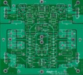
Since many builders of the Aleph-X will choose a version with more than 4 mosfets per channel, the use of the Extension points on the PCB will become important to many.
Here is a picture of the PCB with a numbering from EA1 up to EG2.
Maybe someone experienced with construction of a highpower Aleph-X and these PCB's can give us a short list of how one has to connect these extensions.
EA1 connects with ....
EA2 connects with ....
EB1 connects with ....
EB2 connects with ....
etc. etc.
Thanks in advance!
Attachments
I never thought we needed to include these connection in the board but it didn't hurt anything.
In short, I would only use the EXT before the gate of the mosfet, the EB's for the active CCS, and the EE's points to run the McMillian resistor back to the differential, R46 and 47, I think. am I forgetting something?
The high current + and - rail, the source and the output resistors should be mounted on an approriate PCB or wired p2p like many I have seen here.
It makes alot more sense to run large cross section wire directly from the capacitors to the bank of output transistors rather than going through the PCB traces.
grataku said:I never thought we needed to include these connection in the board but it didn't hurt anything.
In short, I would only use the EXT before the gate of the mosfet, the EB's for the active CCS, and the EE's points to run the McMillian resistor back to the differential, R46 and 47, I think. am I forgetting something?
The high current + and - rail, the source and the output resistors should be mounted on an approriate PCB or wired p2p like many I have seen here.
It makes alot more sense to run large cross section wire directly from the capacitors to the bank of output transistors rather than going through the PCB traces.
If you are using Dale's output boards, Where would you pick up the Sense line? The Drain connection is easy enough to connect to the rails but I thought the Source had to be picked up from EB1 and EB2? That takes care of the positive side, but I am thoroughly confused by how to hook up Dales boards on the negative side. It would be so much easier to label the EXT as Gate, Drain, Source and Sense I guess.
Anthony
When using multiple output pairs per side, is the gate of the MPSA18 connected to just Q1 or also to its parallelled brethren?
I'm assuming that you mean the MPSA18 riding herd on the current source. It only needs to see the first one.
Ditto for the MPSA18 monitoring the output (i.e. the bottom) MOSFET.
Grey
Ditto for the MPSA18 monitoring the output (i.e. the bottom) MOSFET.
Grey
akb1212:
Please see my reply regarding R11 and R33 here . Obviously, I cannot debug Blitz's circuit in person, but I have speculated on some posible causes of his troubles, and made some comments about the value of R11 / R33. 47K should be the correct value, and I would not use 4.7K. However, something a little smaller, such as 25K or 30K may be in order for transistors substituted in place of MPSA18, if their h(fe) is too low... I'm not sure... if you're not building the standard version of the circuit (including supply rail voltages), this should be simulated or carefully calculated beforehand anyway, using the appropriate datasheets. If you want to play safe, build the standard version and just stick with MPSA18's... they're cheap enough.
When first powering up the circuit, V1 and V3 should be set to 0 ohms so that the bias currents are lowest, then subsequently adjusted from there as the amp warms up, and you have verified correct operation of the circuit. As I mention in the Aleph-X wiki, it's not a bad idea to build the amp with all components except for the power transistors, then power that part up to make sure the diff pair and current source work properly.
Prune:
R18(28) and R19(29) are lower, since this works a bit better (apparently... can't remember anymore who made this mod) with the capacitance of the '9610 gates, and gives higher gain. There should be no problem with this change... 10K is a pretty good value here. I would be tempted to decrease the value of R16(30) if I wanted less gain.
Lucas_G:
I give a complete description of how to use the EXT connections in the wiki page ... hmm... wiki seems to be down right now, so I don't have the url handy. Anyway, it's under the Amplifiers -> Pass Labs section. Note there are two EXT pads you missed... close to EA1 and EA2. Basically, I tried to put enough EXT points to be as flexible as possible with parts that people may want to connect off-PCB.
grataku:
Personally, I wouldn't hesitate to use the EXT points for the power rails, if only to retain the nice symmetry of the PCB layout around the rail feed points, and to keep the wiring clean and tidy. I don't think there will be any issue with the current handling of the PCB... remember, that's 2oz copper, on both sides - not your standard PCB trace by any measure. I figure they'd handle 15-20A with ease.
Isn't it safer to use 4.7k? As per Grey's post: "Increasing resistance increases the bias current" So, when starting with a lower value, there's still plenty of room to trim.hifiZen said:47K should be the correct value, and I would not use 4.7K.
On the sim I came out around 52k for a bias of 6A and about 37k for 5A.
That is 4.7k + the 100k trimpot at 47k or 4.7k + the trimpot at 32k.
Making the 4.7k a 47k would give little room to trim.
Besides that, when firing up the amp, one can start with a very low bias which reduces the chance to damage things 😕
/Hugo 🙂
Ah, yeah that's true... wasn't thinking about the 100K pot... hehe. OK I'll retract my previous statement about using 4.7K there. Did you simulate with MPSA18 or BC550? Both?
problem
Aleph-X with 15V power supply. Power supply is working properly.
turning on the amp i get 24V on the +V rail and like 3V on the -V.
Q1 & Q10 are giving normal VGS readings, Q2 & Q11 or not turning on.
I quickly powered off, and looked everything over again... nothing
obvious to be seen.
I didn't take a lot of readings due to the abnormal rail voltages.
nothing seems to have blown - all FETS are still fine.
top left FET is using a ceramic heat pad, that's why you can't
see it... it is insulated though...
the differential pair are not sharing a heatsink, 'cause i don't have
any nylon screws... this was just a quick test to see that i was
getting proper running voltages.
any ideas before i start replacing everything?
Attachments
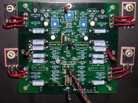
Perhaps you broke one of the output devices when you soldered them in. Am surprised that you didn't just solde them right to the board and eliminate any extra effect the wiring might have. Have you made any quick resistance checks of the OP devices yet? Loading down the supply that much means either a supply problem or a big fat short someplace.
Mark
Mark
Is j1a /j1b installed? I can't see it clearly on your picture. Aah I see it's installed already. I have also connected the fets with wires to my board but I installed the soure-resistor directly on the mosfet.
I also would recommend installing r46 and r47, don't think it is your problem though.
I also would recommend installing r46 and r47, don't think it is your problem though.
Well, the PSU is wired wrong... i have the secondaries wired in
series. Will fix tomorrow. Just when you think you kind of
know what you're doing... i'm pretty embarrassed. 🙁
(the above setup is just for testing purposes. Final assembly will
have the fets soldered directly to the PCB.)
series. Will fix tomorrow. Just when you think you kind of
know what you're doing... i'm pretty embarrassed. 🙁
(the above setup is just for testing purposes. Final assembly will
have the fets soldered directly to the PCB.)
With the MPSA18 the value of R11/R33 can be raised with 4.1k, all other things being equal, meaning the 4.7k would be a theoretical 8.8k to get the same bias settings.hifiZen said:Did you simulate with MPSA18 or BC550? Both?
Of course this is simulation only.
/Hugo 🙂
I'm not too eager to overcrowd threads with sim results.Prune said:Would you kindly post your simulation files?
This http://www.diyaudio.com/forums/showthread.php?postid=329624#post329624 might give you an idea of the measurements. Keep in mind that this is only theory and only applies to Blitz’s amp.
/Hugo 🙂
i did figure out that my problem was with the power supply. I had
forgotten to connect the transformer to ground... yikes.
All i can say is it was kinda late...
the circuit does work now though - now i'm just pondering how
many watts i want to go for - seeing as the transformers i have
on hand are only giving me 13.5 volt rails.
forgotten to connect the transformer to ground... yikes.
All i can say is it was kinda late...
the circuit does work now though - now i'm just pondering how
many watts i want to go for - seeing as the transformers i have
on hand are only giving me 13.5 volt rails.
Moe,
I'd be curious to know what your actual operating current is when all is running correctly. I'm about to fire up my first channel of "Stock" Aleph X. I'm going to use a rather large 32+32 volt 680va toroid that I have and run it down on a variac to get the 15+15 volt DC rails, get it functioning correctly then go from there to a larger version. I matched 75 mosfets last night to 5 digits....... It can be done but I am seeing double tonight so am taking a break from all this .
.
Mark
P.S. you'd be surprised how many pairs I've got to within 25 mv tolerance...... hopefully this will help make the dc offset very low.
I'd be curious to know what your actual operating current is when all is running correctly. I'm about to fire up my first channel of "Stock" Aleph X. I'm going to use a rather large 32+32 volt 680va toroid that I have and run it down on a variac to get the 15+15 volt DC rails, get it functioning correctly then go from there to a larger version. I matched 75 mosfets last night to 5 digits....... It can be done but I am seeing double tonight so am taking a break from all this
.Mark
P.S. you'd be surprised how many pairs I've got to within 25 mv tolerance...... hopefully this will help make the dc offset very low.
We both know that 5 is a waste of at least two digits, but then
what are hobbies for? 😉
The reason for this is that you really can't expect even 3 digit
tracking in real life.
We match to 10 mV in production with no effort, but I will repeat
again that there is no reason to lose sleep if you can do any
better than .1 Volt, especially in the circuits where there is .47
ohm or more on the Source pin.
Nelson,
I absolutely agree that the last two digits really don't even count. However, it was a wonderful evening and I rarely pull out the old Racal 5003.... I was just way too tempted...
Mark
I absolutely agree that the last two digits really don't even count. However, it was a wonderful evening and I rarely pull out the old Racal 5003.... I was just way too tempted...
Mark
- Home
- Amplifiers
- Pass Labs
- Aleph-X builder's thread