I have used motorun caps for crossowers, I have some 25uF but only 2 of them. Anyhow the 10uf wima mkp10 250v where the largest I could fit between kemet caps and the top plate. What is the theory regarding bypassing the electrolyts, why is it necessary and for that matter why large motorrun caps?
primarily better sleep
secondary better handling of transients , so hopefully tiny details
it also depends of wiring , pretty much every small detail in power delivery routes
it's easy to become obsessed with that , so one's measure is task to find
")
translation of all above - just do it , and forget that issue
secondary better handling of transients , so hopefully tiny details
it also depends of wiring , pretty much every small detail in power delivery routes
it's easy to become obsessed with that , so one's measure is task to find
translation of all above - just do it , and forget that issue
btw. worth noting ..... at least from my perspective :
Papa's B1 , and all iterations with same level of simplicity - are cheap way to high end sound (in positive meaning)
if you want absolute level with same approach , then DC coupling is a must , with elaborate PSU (ZM preferring shunt regs) , also decent pcb
so , B1 and Boozhound buffer can give you general taste of things
if you do it in more proper way , it'll work and sound better
if nothing else , you'll have few evenings of great fun , building it
ZM are you hinting at the pumpkin variations ( pumpkin and shunty - you published before me ) ? Id like to build a ss preamp at some point in time. I need to sort out phono and dac first.
@silasmellor see picture in current tread #2983 Official M2 schematic The wimas are just connected across tha last 4 caps.
) ? Id like to build a ss preamp at some point in time. I need to sort out phono and dac first. @silasmellor see picture in current tread #2983 Official M2 schematic The wimas are just connected across tha last 4 caps.
btw. worth noting ..... at least from my perspective :
Papa's B1 , and all iterations with same level of simplicity - are cheap way to high end sound (in positive meaning)
if you want absolute level with same approach , then DC coupling is a must , with elaborate PSU (ZM preferring shunt regs) , also decent pcb
so , B1 and Boozhound buffer can give you general taste of things
if you do it in more proper way , it'll work and sound better
if nothing else , you'll have few evenings of great fun , building it
Pumpkin and Shunty are older project ... primary intended as thingie to enable balanced F4 to go Berserk
what I meant is looking at concept of Iron Pre and Iron Pumpkin (both in plural - SE and Bal iterations)
everyone can make them , concept is old as telephone , and if you have few JFets laying around , some nice repeater xformer from surplus (or Edcor , Jensen , Cinemag) or decent AVC ...... you can make it even on veroboard , even tweaking it here and there with time
so , nothing new under the sun , well worth to roll a stone or two from time to time , looking what's under ...... and what's nice , often you have all parts in drawer already
Sorry I got lost in the pumpkin & iron variations. At some point in time I would like to have a fully remote - iron turtle pumpkin variation pre
And yes I probable already have many of the parts make a DCB1 type buffer for my autoformers other than the supply parts. Mesmerizer is one, your Iron pres are also an option. I really get lost in the many threads here.
And yes I probable already have many of the parts make a DCB1 type buffer for my autoformers other than the supply parts. Mesmerizer is one, your Iron pres are also an option. I really get lost in the many threads here.
Last edited:
Right channel is running away
I have an issue with my M2 bulid on TeaBag's boards. Left channel is fine 0.62V across R13/R14, but right channel goes to 0.75V, stays there for a few minutes and then runs 1V...1.5V...2V. Any ideas? I have replaced 4N35, but no difference...
I have an issue with my M2 bulid on TeaBag's boards. Left channel is fine 0.62V across R13/R14, but right channel goes to 0.75V, stays there for a few minutes and then runs 1V...1.5V...2V. Any ideas? I have replaced 4N35, but no difference...
re: Right channel is running away
Maybe a promising first line of inquiry, might be to learn whether the "input side" of the bias control loop is operating correctly. That's R10-R14 plus Q5-Q7, the complete circuit which includes the LED portion of the optoisolator.
It might be extremely revealing, to measure the LED current for the good channel and also for the bad channel. You can get this by measuring the voltage across R11, and then use Ohm's Law: Current = Voltage/Resistance.
In this case, LED current = R11 current = R11_voltage / R11_resistance and the M2 schematic tells us that R11 = 221 ohms.
Are the LED currents wildly different between the good channel and the bad channel? If so that's a giant clue.
It could also provide more insight, to directly measure the LED voltage (positive DMM lead on Q5 pin1, negative DMM lead on Q5 pin2) for the good channel and also for the bad channel. A screwy LED voltage on the bad channel, provides more clues.
BTW you'll want to ask for debug suggestions & recommendations from people who have successfully built M2s using the Tea-bag PCBs. They may have encountered this exact problem already, and can hand you a solution straightaway.
_
Attachments
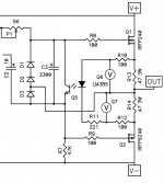
M2x offers the PCB option of installing a 220uF 10V bipolar coupling capacitor (Nichicon UES) in series between JFET buffer and Edcor transformer primary. The M2 circuitry already includes one coupling capacitor, it's called "C2" in the official schematic attached to post #1 of this thread. If you don't mind one coupling capacitor, surely you won't mind two of them??
It also offers the possibility of adjusting the trimpot for just-the-right-amount of 2nd order harmonic distortion (if you go for that sort of thing), having just the right phase, without worrying about the resulting output offset voltage. The new 220uF removes every trace of output offset voltage. Twirl the trimmer however you want; output offset remains zero.
It also offers the possibility of adjusting the trimpot for just-the-right-amount of 2nd order harmonic distortion (if you go for that sort of thing), having just the right phase, without worrying about the resulting output offset voltage. The new 220uF removes every trace of output offset voltage. Twirl the trimmer however you want; output offset remains zero.
- Home
- Amplifiers
- Pass Labs
- Official M2 schematic