Papa used 4x15mF/rail but it's for stereo, since you have a mono psu,it's already more than commercial product. But no too big caps for class a rite, because you have 800VA which is huge so why not make a huge caps too
I like to oversize things! But I guess 800VA is way over I must admit! I dont know where my head was last year when I ordered them! 🙂
Please take a look at post 1008 or link http://www.diyaudio.com/forums/pass-labs/281520-official-m2-schematic-101.html#post4664760
This is the signal i get on speakers. The input is dead queit also when shorting it the signal remains on speakers. Only difference is when I move the toroids away from the circuit I get different modulation and volume.
Thanks
On the psu do you have your GND return to chassis with CL60 ?
The signal is certainly high frequency but aperiodic which is odd.
So,it looks clear that it's the toroids - did you try Nelson's trick of rotating the toroids till the hum goes away ?
..ok had a look at your previous posts...and answered my own question.
You have transformers with shield between primary and secondary so it's maybe just a fact that the magnetic field of these monsters is to strong to be so close to the PCB.
You have transformers with shield between primary and secondary so it's maybe just a fact that the magnetic field of these monsters is to strong to be so close to the PCB.
Yes I tried also to rotate it and the modulation of the signal is a little different.
Today I played whit different position of toroids and its clear that I need to move them 10cm out of the enclosure to get almost no hum but still... This toroids hum also so I put them on aluminium plate and I get almost the same sound from it as is in speakers...I tried a DC block but no change, they just hum...🙂 Odd experience so far! It looks like the quality of toroids is the most important thing! This were made by toroidy.pl.
Today I played whit different position of toroids and its clear that I need to move them 10cm out of the enclosure to get almost no hum but still... This toroids hum also so I put them on aluminium plate and I get almost the same sound from it as is in speakers...I tried a DC block but no change, they just hum...🙂 Odd experience so far! It looks like the quality of toroids is the most important thing! This were made by toroidy.pl.
Yes I tried also to rotate it and the modulation of the signal is a little different.
Today I played whit different position of toroids and its clear that I need to move them 10cm out of the enclosure to get almost no hum but still...Odd experience so far! It looks like the quality of toroids is the most important thing! This were made by toroidy.pl.
That's a great point! I have a Piltron toroid in my F6, it's about 25% smaller in size than the Antek. I think I'll try swapping them and squeezing it another 1/2" further forward.
change that 10uF for start
though , if crackling is nonexistent with input shorted ........ recheck all solder joints
most important is that you excluded input JFtes and xformers from list of suspects , rest is peanuts
Thanks everyone for the help. It's fixed. I used my meager oscilloscope skills and found the noise everywhere including at the input with no source. It had to be the Jfets. I replaced them again with a pair from a working F5 board. The bad ones test fine with my Peak analyzer so now I'll have to go through my stash of sk170/j74 and see if I have been sold fakes. They were matched for IDSS so I'm not sure...
Can you post measurements and a picturee ofthe bad jfet?
I'm courious if we can spot, if it's a bad device or fake. I have a Peak DCA75 and hopefully some original jfets...
I'm courious if we can spot, if it's a bad device or fake. I have a Peak DCA75 and hopefully some original jfets...
If you look at known good jfets and suspicious ones with a loupe you can often see the differences and sometime you can actually faintly see the original numbers even though the were ground off. Now to be sure I buy the store LSK's, they work great.
Hi ZUM911,
Good to see you've found the problem.
When you said, the bad jfets tested fine, what information did the Peak analyzer
give you? Are you able to do curve traces of the jfets.
If I read your posts correctly, both the first and second jfet sets were bad. Did
they come from the same source as your good channel ones?
Dennis
New Power supply and Layout
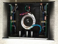
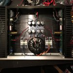
I spent a day getting this sorted but It was well worth the change. Now the HUM is present at 2' vs 20'. The 300VA Piltron doesn't have a shield wire but is much quieter in this configuration. Now it's cooking time.
First photo is Antek 400VA second 300VA Piltron.
I spent a day getting this sorted but It was well worth the change. Now the HUM is present at 2' vs 20'. The 300VA Piltron doesn't have a shield wire but is much quieter in this configuration. Now it's cooking time.
First photo is Antek 400VA second 300VA Piltron.
Attachments
I spent a day getting this sorted but It was well worth the change. Now the HUM is present at 2' vs 20'. The 300VA Piltron doesn't have a shield wire but is much quieter in this configuration. Now it's cooking time.
First photo is Antek 400VA second 300VA Piltron.
Congrats...you will note that is the configuration NP uses...i use it as well.
Because transformer is furthest away from input !!!
😎
I spent a day getting this sorted but It was well worth the change. Now the HUM is present at 2' vs 20'. The 300VA Piltron doesn't have a shield wire but is much quieter in this configuration. Now it's cooking time.
First photo is Antek 400VA second 300VA Piltron.
Interesting PSU board. Who made it?
Hi ZUM911,
Good to see you've found the problem.
When you said, the bad jfets tested fine, what information did the Peak analyzer
give you? Are you able to do curve traces of the jfets.
If I read your posts correctly, both the first and second jfet sets were bad. Did
they come from the same source as your good channel ones?
Dennis
The analyzer basically says its good or bad and identifies the pins. I started gathering jfets when the sk170 and j74 were discontinued and got them from a few different sources. Unfortunately they are mixed now after I tested them.
I don't have a curve tracer and only did IDSS matching.
In a few days I'll test the bad ones again and have a closer look to see if there are anything funny about them.
Let's talk Chassis for the M2
Would the 300mm 4U Deluxe be suitable or is the 5U better suited
Would the 300mm 4U Deluxe be suitable or is the 5U better suited
Last edited:
The 4U is plenty big enough with only 2 mosfets per heat sink.
Thanks
Since you sweet talked me to build this amp - And since I trust your opinion on how it sounds with our similar horn speakers so - I'm doing a shopping list as I wait for teabags PCB boards to be manufactured and shipped.
FR
The 4U is plenty big enough with only 2 mosfets per heat sink.
Thanks
Since you sweet talked me to build this amp - And since I trust your opinion on how it sounds with our similar horn speakers so - I'm doing a shopping list as I wait for teabags PCB boards to bemanufactured and shipped.
FR
Congratulations!
What does "hum at 2' vs 20' " mean?
I interpreted it to mean 2 feet vs 20 feet.
- Home
- Amplifiers
- Pass Labs
- Official M2 schematic