Yes, noisy with both source and no source. Loudest with no source, less with source connected and no noise at all when input is shorted.
magnifier and ohmmeter ......... and good luck
check thoroughly all wire ends on xformer
can you post some pictures ?
check thoroughly all wire ends on xformer
can you post some pictures ?
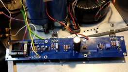
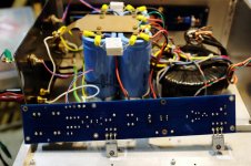
A couple pics.
I've swapped the Edcor trannys around and still noisy on the left so the tranny is good. Only things I haven't swapped are the caps and resistors. The resistors were all measured going in and the caps read good with my LCR meter in circuit.
I've swapped the Edcor trannys around and still noisy on the left so the tranny is good. Only things I haven't swapped are the caps and resistors. The resistors were all measured going in and the caps read good with my LCR meter in circuit.
Attachments
change that 10uF for start
though , if crackling is nonexistent with input shorted ........ recheck all solder joints
most important is that you excluded input JFtes and xformers from list of suspects , rest is peanuts
though , if crackling is nonexistent with input shorted ........ recheck all solder joints
most important is that you excluded input JFtes and xformers from list of suspects , rest is peanuts
It sounds like an intermittent connection somewhere. A bad RCA cable connection to the RCA input will do much the same thing. Swap inputs and if it were me I would pull both input and output grounds and attache them to the Star ground. Being the noise goes away when shorted I would be mighty suspicious of the RCA input connector.
Yes, same power for both channels. Caps is all I have left to replace. I reflowed the joints earlier. I've got star ground at the output, incoming ground goes to the board but this not a ground loop hum.
If there is enough interest , buyers, the store may be persuaded to have boards made and sell them. It is the best sounding of the 4 FW's I have built but this is with horns.
Interest is obvious, this thread and two group buys...
Russellc
my feeling is that it is either bad cable before input or cracked pad-track link due to temp diferential...look for that ...it's super hard to spot and no matter how many times you redo the pad resolder it will not go away.
you have 2 choices for this....track the crackle from input to output and once found scrape a bit of track near pad on all pads arround that spot and resolder....second : use brute force method and do this to all pads.
you have 2 choices for this....track the crackle from input to output and once found scrape a bit of track near pad on all pads arround that spot and resolder....second : use brute force method and do this to all pads.
Last edited:
Thanks CeeVee, I never thought about the pads cracking away from the traces. I've gone over the board with a magnifier but wasn't specifically looking at that. I'll replace caps first and then it's the pads.
I tried also the inductor on top version but the buzz 50hz results are the same! Very low volume I have to put my ears very close to the speakers but anyway I can hear it thats the problem! I think the main problem are the two big 800VA toroids witch I cant move farther away from the amplifier boards and PSU.
So the plan is to move the transformers, caps and inductors to a separate chassis so that only the amplifier will remain in this chassis. BUT how long (i know as short as possible) but can they be 1m long I mean the cable from the psu to the amp? And the size of the decoupling caps in amplifier chassis? I have 1000uF 50V elnas available? So I need your advice what to do? Otherwise the M2 sounds wonderful!!!
So the plan is to move the transformers, caps and inductors to a separate chassis so that only the amplifier will remain in this chassis. BUT how long (i know as short as possible) but can they be 1m long I mean the cable from the psu to the amp? And the size of the decoupling caps in amplifier chassis? I have 1000uF 50V elnas available? So I need your advice what to do? Otherwise the M2 sounds wonderful!!!
I tried also the inductor on top version but the buzz 50hz results are the same! Very low volume I have to put my ears very close to the speakers but anyway I can hear it thats the problem! I think the main problem are the two big 800VA toroids witch I cant move farther away from the amplifier boards and PSU.
So the plan is to move the transformers, caps and inductors to a separate chassis so that only the amplifier will remain in this chassis. BUT how long (i know as short as possible) but can they be 1m long I mean the cable from the psu to the amp? And the size of the decoupling caps in amplifier chassis? I have 1000uF 50V elnas available? So I need your advice what to do? Otherwise the M2 sounds wonderful!!!
Copy from our Papa master on Xs amplifier, use PowerCon and 1m cable should be good. Remember that inductor is just a very longg cable. 10mF should be enough but not 1mF. Well you can check what i've done if you think its reasonable.
www.diyaudio.com/forums/pass-labs/166784-pictures-your-diy-pass-amplifier-351.html#post4670010
I see. Thank you guys. Right now I use 2x 44000uF (2x 22000uF) per rail.
So I could split it to get 22mF + 10mH inductor + 44mF and on other chassis 22mF. I think that would be sufficient or?
So I could split it to get 22mF + 10mH inductor + 44mF and on other chassis 22mF. I think that would be sufficient or?
Papa used 4x15mF/rail but it's for stereo, since you have a mono psu,it's already more than commercial product. But no too big caps for class a rite, because you have 800VA which is huge so why not make a huge caps too
maybe we could all reason better if you could give us a scope image of the signal that causes the effect you refer....feed the amp with a sine wave for example and get the image of the output.
It is dificult for me to believe that the trafos or caps are doing it...trafos are huge by the way ...why so big ?...half that is plenty.
Anyway that's OT....would be great to see a picture of the offending singal...even better with both channels in simultaneous....
It is dificult for me to believe that the trafos or caps are doing it...trafos are huge by the way ...why so big ?...half that is plenty.
Anyway that's OT....would be great to see a picture of the offending singal...even better with both channels in simultaneous....
Please take a look at post 1008 or link http://www.diyaudio.com/forums/pass-labs/281520-official-m2-schematic-101.html#post4664760
This is the signal i get on speakers. The input is dead queit also when shorting it the signal remains on speakers. Only difference is when I move the toroids away from the circuit I get different modulation and volume.
This is the signal i get on speakers. The input is dead queit also when shorting it the signal remains on speakers. Only difference is when I move the toroids away from the circuit I get different modulation and volume.
- Home
- Amplifiers
- Pass Labs
- Official M2 schematic