Usually AC switch noise is suppressed by some capacitance across the
AC line(s) and across the switch. You would want ac line rated
capacitors on the order of .1uF
The only X1/Y2 rated cap I have is 3300pf. Any chance this would work?
Your loud pop is if you shutting all tuntable power off
or is if your turntable stops for pause or vinyl change ?
Greetings
The turntable motor only has one switch and it pops when switched off.
The turntable motor only has one switch and it pops when switched off.
At my end of musical session i always shut down first my amp after preamplifier and at the end audio source. Non pop this way
")
At my end of musical session i always shut down first my amp after preamplifier and at the end audio source. Non pop this way
I have to use this switch to change records.
Ah ok i understand better now that was my initial question.I have to use this switch to change records.
Btw i see in one recently restored vintage amp two non polarised
AC 250 V ceramics caps around the switch as well.
Attachments
The only X1/Y2 rated cap I have is 3300pf. Any chance this would work?
3,3 nF is small capacitor but if non polarised and voltage OK
maybe you can just try solder them and hear if pop is gone.
If not find adequate 0.1 uF leater.
Edit : i remember in the past i find switch contact or push botton who was oxyded and make noise but i clean that with special spray electronic contact cleaner and was back quiet. Find new equivalent part is the great solution non doubt
Greetings
Find new equivalent part is the great solution non doubt
Was checking the VPI forums and it seems quite o few people have had the same problem with their turntables. Apparently VPI will send me the proper part if I contact the right person there.
Alright, I'm done clogging up this thread with my turntable issue.
BTW this M2 is a beautiful sounding amplifier. Wonderfull midrange with a slightly softer high end, but still very detailed. I thought I might loose some bass but I really haven't noticed that. Pretty much as described by others. For me it works especially good with pop/rock music some of which is recorded a little hot. On well recorded music I do miss the little bit of sparkle on the high end the F4 has with my system. Good thing I have both...except for the fact that the F4 is on loan with my brother.
The turntable motor only has one switch and it pops when switched off.
Try putting your 3300pf cap across the switch.
Try putting your 3300pf cap across the switch.
I replaced the 1000pf cap that was there with the 3300pf I had...quiet as a church mouse!
I replaced the 1000pf cap that was there with the 3300pf I had...quiet as a church mouse!
On the turntable switch? Or amp? I assumed you meant turntable switch....
Russellc
I replaced the 1000pf cap that was there with the 3300pf I had...quiet as a church mouse!
Hahaha
 keep mouse far away from the cats !
Other cool thing you can do is install snubber resistor and caps.
See empty dedicated places in your universal psu pcb's.
You need test individualy your toroid with Quasimodo jig.
That give you finnaly very nice for the music psu low noise floor.
M2 want this snubber stuff

See in this Mark Johnson helpful fantastic thread :
Simple, no-math transformer snubber using Quasimodo test-jig
Cheapo modo version if you ready have some of the components on work bench.
Have a nice sunday
Other cool thing you can do is install snubber resistor and caps.
Yes, I have a Quasimodo. I haven't installed snubbers on the M2 yet but I plan to!
Yes, I have a Quasimodo. I haven't installed snubbers on the M2 yet but I plan to!
Yes Yummy
Attachments


I re-purposed my F5 using M2 boards from Tea-Bag. They are in a 5U chassis which is a bit overkill, but the upside is no hum due to the auto-former being quite a distance from the mains transformer.
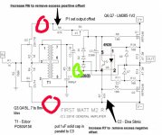
Getting the offset to null was fun...not. My offset was negative so I ended up pulling the boards and soldering sockets in place of R7. Then searching through resistors I had on hand ending up with 47.5k and 220R in series measuring 47.72k. This gave me enough adjustment with P1=5k, and R6 remaining at 47k. Then I just soldered the resistors into the sockets. It sounds simple, but it was a lot of trial and error.
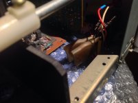
Here are the pics to prove it really happened:
View attachment 630900 View attachment 630901 View attachment 630902
@ KevinHeem
What happen with music if you don't use Jensen JT-11P-1 at RCA inputs ??
- Home
- Amplifiers
- Pass Labs
- Official M2 schematic