got it fixed I resoldered the pot and changed the 10k res, and I flipped the led,
it was in correctly - to - and + to + but didn't work until I flipped it not sure what's going on there but it works now, bias set to 500 mv and offset 0
very stable,,.. time for a sound test 🙂
The cathode of an LED should be connected to the most negative voltage source.
As such in the (-) 24V dc rail, the cathode should be connected to that side and the anode connected to ground. That is why your LED worked when you flipped it.
In the (+) 24V dc rail, the cathode is connected to ground and the anode is connected to the rail side. If you understand how electrons flow, this will make more sense.
Hope that helps.
Best,
Anand.
I'm about to build an F6. Received the PCB:s and line transformers last week and components are underway. I have what I consider to be a resonabel box to house the build but need to add heatsinks to it. What are a rule of thumb K/W requirement for an F6 for each channel?
Last edited:
strongbow60 ,
You can check out the Modushop heatsink specs at the diyAudio store for 4U x 300mm and 3U x 400mm dimensions. Larger (e.g. 4U x 400 mm) will work of course .
P.S. Zen Mod has already replied... always quickest to respond... 😀
You can check out the Modushop heatsink specs at the diyAudio store for 4U x 300mm and 3U x 400mm dimensions. Larger (e.g. 4U x 400 mm) will work of course .
P.S. Zen Mod has already replied... always quickest to respond... 😀
Last edited:
You can look up the heatsink specifications when you have an idea of what to look for so ..
The F6 range dissipates most of the class A power into the heatsink via the main output transistors and if you bias these at the approx 1.6A, and the power supply rail voltages are +/- 23v, then the power to be dissipated is simple 2 x 23 x 1.6 (= 74W) for each channel.
Then, estimating the temperature rise - if your room temp when the amp is in use doesn't get much above 30*C, your amp will function perfectly well with a temp rise of 20*C (50*C) with 75w pumping into it so, the heatsink rating is 20/75 = 0.27*C/W.
That gives you an approximate aiming point - there are a few other details about transistor heat transfer, pads, etc but this rough guide will get you reasonably close
The 4U x 300mm modushop unit (fins are 177mm long = a 7" high box) is a bit more efficient radiator than that at about 0.22*C/W and will produce a temp rise of about 16*C.
- the 3U 'sinks are 132mm long (the fin length or case height) and 0.32*C/w so will run at about a 25*C temp rise, a bit hotter.
The 400mm long heatsinks are naturally better heat radiators and will have a thermal resistance around the 0.2*C/W which will give you a temp rise of about 0.2 x75 = 15*C rise
It's generally recommended to run your amp cooler, hence the bigger/longer heatsinks.
If size is a problem, you can cool the sinks with a fan (there's plenty of 'noiseless' computer fans) and/or use a 'tunnel heatsink', for example
Oh yes - for those people like me who are mystified by this 1U, 2U and so forth, the measurement of 1U is actually 1.73" or 44mm, so 3u is 132mm (5.2"), 4U is 176mm (7"), etc
This is mainly a pro-audio equipment rack mount standard measurement probably set by transformer size or something in the "old days" and it just stayed that way!
This is mainly a pro-audio equipment rack mount standard measurement probably set by transformer size or something in the "old days" and it just stayed that way!
Thanks for a for a very thorough reply jameshillj. This is exactly the information I was after. I did the mental calculation myself but wasn't sure about the bias current.
A 4 u box is a bit on the high side for the intended place, besides the Dissipante box is ugly!
I'm probably go for a 3 U box and active cooling on the inside of the box using two slow rotating fans, but I have to figure out the flow of air first.
An ambient temperature of 22-25C is a resonable assumption where I live, although right now this assumption is tested severely. A .3 K/W and max 30*C rise in temperature is ok I think.
I am very well aware of the U designation for height, being a systems engineer. Rack mounted computers has taken the place of rack mounted audio equipment in my line of work.
"No problemo", as Arnie says! Arnold Schwarzenegger, that is
A couple of the guys here run a computer cooler 'heat-tube' system that seems trouble free - was a bit surprised to see a water cooling circulating system too - imagination unbound!
I had another F5 that ran rather hot indeed at about 60*C in summer, and the power Fets were a lot hotter than that, but it never 'missed a beat', as they say and still working after quite a few years - very sturdy fets those IRFPs - I did add Patrick's (EUVL) jfet cooler 'sinks' on the 2sk/2sjs for safety - neat little things ...
Oh, something that might help - I made sure the baseplate (bottom of amp) had cutouts next to the heatsinks so had increased air flow in the internal side of the heatsinks.
Ine thing I wasn't too happy about was the extra sized heatsinks in the MSR 860 diodes - I thought these gave a better sound than the bigger 1560s but ran a lot hotter.
Nowadays, I'm using a version of the lt4320 chip synchronous rectifiers (the Prasi pcbs) and also trialing the Micro Audio SMPS with a version of Salas' L-Adapter regulator and very promising results on the F6 indeed....
Thanks for the the pointers. The fans will hopefully take care of the internal heat. I currently have a JLH -69 nockoff running in my main system. This was the inspiration for doing an ACA and F6. Today I got all the components for an ACA build. This will then be the used as model for the F6.
Actually I plan to use a SMPS with a filter and then a few capacitors. One set of filters and caps for each channel. I will have to experiment to see how big the caps:s can be and still get the SMPS to start.
Actually I plan to use a SMPS with a filter and then a few capacitors. One set of filters and caps for each channel. I will have to experiment to see how big the caps:s can be and still get the SMPS to start.
There is a nice simple, fairly high current SMPS filter being used in the new DIY Sony VFET amp. It’s not available separately in the store, but it would be straightforward to build on a protoboard. One for each channel should do the trick.
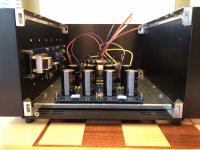
Have you placed output transistors on the both heatsinks? I can't see any wire from the board to another side of the chassis.
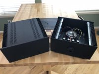
Building them as single ended monoblocks. One channel/signal board per chassis. Considering going balanced down the road and set things up so it is easy to do (2nd transformer, 2nd psu board, 2nd signal board). Will have to replace or tap the heatsink but everything else is bolt on.
As I used the PSU boards per the build thread for a stereo set, I may have an overkill capacitor bank but learning as I go.
As I used the PSU boards per the build thread for a stereo set, I may have an overkill capacitor bank but learning as I go.
Attachments
Last edited:
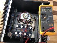
Suggest you add a thermistor or 'soft-start' circuit for that large capacitor load, and also include another one for the 'ground lift' too as per the basic F6 power supply diagram - perhaps you can create some space for this if you can move the transformer & pcb towards the front or to one side...
Thanks! I'm researching that bit tonight in prep for my next Mouser order. very used to vacuum tubes so still adjusting from high voltage to high current thinking.
I think there is room there without having to move anything. There is more space than the picture lets on. If not, moving one of the diode bridges should do the trick (he types hopefully).
I think there is room there without having to move anything. There is more space than the picture lets on. If not, moving one of the diode bridges should do the trick (he types hopefully).
CL 60's are the thermistors to use if I remember correctly.
https://www.mouser.com/ProductDetail/Amphenol-Advanced-Sensors/CL-60?qs=w3gjcs3NwciEQjXGFRAAAA==
I ordered a few extra of them as they are a hot item in all of these designs. If you are doing the 15000uf caps then I think you can get away without the soft start. I am not an expert though. I have the 18000uf caps (I think 6l6 suggested them a while back) and haven't had any transformer issues so far. I only have the CL-60s on the transformer inputs and ground to the power supply board.
Youn could also use Ametherm SL22-20007 https://www.mouser.com/datasheet/2/600/SL2220007-276391.pdf
if you can't get the CL-60s.
I prefer Mark Johnson's Softstart PCB: low voltage On-Off switch drives AC mains relay \ includes soft start .. H9KPXG
The problem with "Thermistors" is that if you turn the amp off and then turn it back on without waiting for the CL-60 to cool off you have no inrush limiting. Then the inrush Gotcha! Themistors have no such problems for ground lift and are recommended for that.
Copy that and thanks, Mike.
Do you know what issues arise with the transformer? I'm using Hammonds with a 220VAC rating since it is one signal board per power supply. Guessing there will be a bit of current limiting due to the lower VAC limit but don't know if it will cause a hardship with current transients on the transformer (windings buzzing loose, thermal overload, etc.)
Vacuum tube rectifiers make all this so much easier but that's a different beast with its own issues.
- Home
- Amplifiers
- Pass Labs
- F6 Illustrated Build Guide