meanie,
Very well executed build - congratulations!
It is also notable that early adopters like you and Vunce are trying out SMPS in their Class A builds, and I am sure others will be observing. On the visual side, it looks like there's lots of empty space with the chassis - nice! 🙂 Btw, what are the chassis and heat-sink dimensions?
Kudos to Cresnet with coming out with this solution!
Based on experience of the early adopters (and of course measurements), Class A amps with SMPS power supplies also might become quite popular in the coming years. Building the PSU is often a challenge for a novice DIYer, and a readymade SMPS can make it more "plug and play".
I have also implemented the 3 x Green LED mod suggested by 2 Pico Dumbs. Still need to try out the different MOSFETs.
Oh yes, Vunce is the early adopter, i am way behind.
Here is the link to the chassis:
KYYSLB DIY Home Audio Box Case 285*150*370mm WA109 Aluminum Amplifier Chassis Class A Amplifier Pure Post amplifier Case|Amplifier| - AliExpress
The Conrad HS dimensions are 350x151x50mm
Smps makes the amp so much lighter, swapping amps is easier.
Here is the link to the chassis:
KYYSLB DIY Home Audio Box Case 285*150*370mm WA109 Aluminum Amplifier Chassis Class A Amplifier Pure Post amplifier Case|Amplifier| - AliExpress
The Conrad HS dimensions are 350x151x50mm
Smps makes the amp so much lighter, swapping amps is easier.
Last edited:
Meanie,
Very well done!
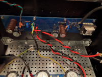
*Very neat, tidy, clean wiring, so repairs are easy if it ever needs it. The OFFSET and BIAS pots are clearly labelled.
*SMPS supplies are cool. Both literally and figuratively.
*I like the bridge rectifier for the ground lift, i.e. ground FAULT, nicely implemented.
*I like how the speaker return goes to the PS ground which is a variant and may be sonically advantageous as well.
*XRK's speaker protection module, nicely done!
Incidentally I spent a significant time of my youth in S'pore, right around Ulu Pandan Road. We still have friends in Ang Mo Kio, Serangoon Rd, etc...
Best,
Anand.
Very well done!
*Very neat, tidy, clean wiring, so repairs are easy if it ever needs it. The OFFSET and BIAS pots are clearly labelled.
*SMPS supplies are cool. Both literally and figuratively.
*I like the bridge rectifier for the ground lift, i.e. ground FAULT, nicely implemented.
*I like how the speaker return goes to the PS ground which is a variant and may be sonically advantageous as well.
*XRK's speaker protection module, nicely done!
Incidentally I spent a significant time of my youth in S'pore, right around Ulu Pandan Road. We still have friends in Ang Mo Kio, Serangoon Rd, etc...
Best,
Anand.
Last edited:
Beautifully done, meanie!
Coincidentally very similar to my nascent F5 build. 😀
Can someone explain the rationale for connecting the bridge rectifier for safety earth? I was planning on just connecting the smps safety earth and the earth pin of the IEC module to a chassis ‘star ground.’ What benefit does the rectifier add?
Coincidentally very similar to my nascent F5 build. 😀
Can someone explain the rationale for connecting the bridge rectifier for safety earth? I was planning on just connecting the smps safety earth and the earth pin of the IEC module to a chassis ‘star ground.’ What benefit does the rectifier add?
Can someone explain the rationale for connecting the bridge rectifier for safety earth? I was planning on just connecting the smps safety earth and the earth pin of the IEC module to a chassis ‘star ground.’ What benefit does the rectifier add?
Minimizes the potential for ground loops and hence one source of hum. Similar to the CL-60 implementation on many FW power supply builds but even more safe.
See here and here for Bonsai's writeups.
Best,
Anand.
Last edited:
I was curious and had to check the site for that Micro-Audio SMPS. It is encouraging (and unusual) to see a switching supply capable of delivering current to a Class A audio amplifier, and accepting large value capacitors on the output. I'm looking forward to hearing more listening impressions as the amp continues to settle in. Especially after 200 hours.
Edited to add:
It might also be interesting to try some separate supply capacitance local to each channel board.
Edited to add:
It might also be interesting to try some separate supply capacitance local to each channel board.
Last edited:
It might also be interesting to try some separate supply capacitance local to each channel board.
Good idea, let me go figure if i can add that neatly on both channels.
Thanks TA
I was curious and had to check the site for that Micro-Audio SMPS. It is encouraging (and unusual) to see a switching supply capable of delivering current to a Class A audio amplifier, and accepting large value capacitors on the output. I'm looking forward to hearing more listening impressions as the amp continues to settle in. Especially after 200 hours.
Edited to add:
It might also be interesting to try some separate supply capacitance local to each channel board.
The next generation of the SMPS for CLASS-A will tolerate around 4A ~ 5A of idle current.
As another design plan is to handle 200000uF ~ 400000uF of extra capacitance at the output of the SMPS.
Lab tests were successful for 160000uF already.
But that revision may take a while to show up, as cooking takes some serious work.
Thanks
Frankly Not understanding the point of using an SMPS here..
over the traditional .. time Proven.. Torroid and Caps power supply.
Was it significantly Less coin to buy ?
over the traditional .. time Proven.. Torroid and Caps power supply.
Was it significantly Less coin to buy ?
I do not speak for those who have already chosen to build a FW amp with an SMPS. I do have some general observations:
a) The switching frequency of SMPS units is much higher (ca. 100 kHz) than the 100 Hz to 120 Hz rectification frequency of linear supplies. This is much easier to filter down to an acceptable level. We can also safely say that there are fewer magnetic and other IM coupling mechanisms for the switching frequency to enter the audio circuits and produce audible distortion as a result.
b) SMPS units are easier to install either internally or externally. They simply require wire hookup to the AC inlet and DC out power rail connections to the channel boards. Having just finished another linear PSU, I can say the difference is marked.
c) SMPS units are much lighter weight, making the resulting amp much easier to move around.
d) Total cost for the SMPS is somewhat less, of course depending on which one is selected vs. possible cost of separate components in the linear PSU.
So far we have a couple demonstrations of SMPS effectiveness in the ACA and the recently released DIY Sony VFET amp. At this point, I can say that I was able to build what I considered sonically superior linear supplies for my later ACA builds, but definitely at higher cost and construction effort. Whether a linear PSU may be sonically superior to the SMPS unit that is included with the DIY Sony VFET kit is still to be determined.
The newer SMPS units being used in the above F6, and in a similar F5 build, look promising. As they say, the proof is in the pudding, and we will wait to hear the listening impressions.
Frankly Not understanding the point of using an SMPS here..
over the traditional .. time Proven.. Torroid and Caps power supply.
Was it significantly Less coin to buy ?
For me, it is about choice and availability.
It is not easy to buy transformers here, even custom windings, I sometimes get quality issues, ie one may hum and the other not, without load!
Buying online, the costs of shipping due to the massive weight, I will have to fork out exorbitant shipping fees.
So I chanced upon another member here who has used Smps successfully, and I decided to try one out. To my amusement, they are not what I read about SMPS and all its quirks.
They are quiet, power up smoothly with a cap bank, fewer wirings to take care of, when assembling an amp, have ready aux voltages for spk protection circuit or even a cooling fan(not needed).
In fact, I have power up my amp using just the SMPS(without cap bank). it sings beautifully too, with no hum and no ground looping issues.
The cap banks are nice to have, I may later run it thru another Cap-multiplier circuit and see how it performs. Hope it powers up the SLB nicely.
The first piece I received tested so well, that I went on to reorder a total of 6 pieces. So all toroids are coming out of my amps, additional filtering may stay put. In my case, SMPS is there to replace my 50hz trannies.
So my point for sharing is, for those who are already on the fence about trying SMPS, this is the time to try one for your ClassA amp, in the event that if you don't like it, at least you tried.
It's about moving forward, E and I laminations are traditionally proven design, why go to toroidal donuts.
Happy tinkering!
How should you modify the layout if you want to build this as a headphone amplifier for the likes of Abyss 1266 and Susvara?
I think
- you can use smaller To-220 mosfets, reduce the curent to 500 mA; this is enough at 60 ohms.
- because of the 83 dB, you can slightly increase the feedback R3 as you like. The open-loop amplification factor is very high, and with 32 ohms you have more feedback than with 8 ohms . . . You can icrease to 220 ohms with ease.
As a side-note, I made my first F6 look-alike in 1995, with one power rail, and an Opamp input - but no feedback. It was scary and never left my workbench; though N Pass later learned me the FB trick & he showed that such amps withouit FB do not inherently sound bad, to the contrary. You can I think safely experiment even with 330 ohms and not use a preamp . .
Nice build meanie.
No massive transformer? or a row of mosfets right angle to the heatsinks these days?
I been repairing Perreaux amps for too long and old school.
No massive transformer? or a row of mosfets right angle to the heatsinks these days?
I been repairing Perreaux amps for too long and old school.
I guess the linear PSU is easier to service than SMPS. Don't like SMPS as they have loop feedback and high voltages. Hard to repair & cheaper to buy a new one. SMPS's are disposable/do not touch in my repair bible.Whether a linear PSU may be sonically superior to the SMPS unit t
Thanks BKnut,
The maker mounted the mosfets on the L bracket, this is his design and i can't comment on that. However, he did ask me to check temp at various part of the smps after 5 hours of continuous operation. Hottest part is the transformer@ 65degC, the rests of the semiconductors were merely 40'ish degC. Well within his safety spec. There is a over current and thermal shut down circuit built in too.
His after sale support is very good and fast, and in any case if i can't repair one, i may have to buy new ones, same goes for a traditional transformer, i wouldn't rewind it too.
When i got time, i wanted to scope the ripples on the smps output to see if there is any high freq oscillations in them.
So far it has been dead silent on the woofer and tweeter.
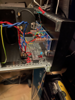
Hi guys, I have some pics of the build i'm just trying to set the bias now
the right Channel set perfect the left channel has an issue
bias set ok to 500 mv but the offset has 17-18v coming through the speaker terminals and the pot does not have an effect something also my led is not on but that could be from soldering to hot.
any thoughts before I take that board out.
the right Channel set perfect the left channel has an issue
bias set ok to 500 mv but the offset has 17-18v coming through the speaker terminals and the pot does not have an effect something also my led is not on but that could be from soldering to hot.
any thoughts before I take that board out.
Attachments
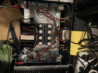
bias trouble and fix
got it fixed I resoldered the pot and changed the 10k res, and I flipped the led,
it was in correctly - to - and + to + but didn't work until I flipped it not sure what's going on there but it works now, bias set to 500 mv and offset 0
very stable,,.. time for a sound test 🙂
got it fixed I resoldered the pot and changed the 10k res, and I flipped the led,
it was in correctly - to - and + to + but didn't work until I flipped it not sure what's going on there but it works now, bias set to 500 mv and offset 0
very stable,,.. time for a sound test 🙂
- Home
- Amplifiers
- Pass Labs
- F6 Illustrated Build Guide