UPS BOM for the v3PSU
Hi. I am new to audio coming over from radio. Lots of similarities and lots of differences. I am working on a build of the clone Pass F6 and am at a complete loss with the UPS BOM for the v3PSU. Can somebody help me with snubber capacitors? I just cannot find what I need to fill out the missing BOM part numbers. And, to make it worse, searching on DigiKey, it's hard to come up with something if you don't have a good match for both farads and volts.
Thanks for the help.
Don
@donhughes111 - Welcome. The input snubber values (caps and resistors) will vary based on the transformer you choose.
Once you've chosen your transformer, post back. Someone will likely help you with the values. If you choose one of the more common Antek models, they have already been tested. AS-4218 or AS-3218 as examples.
Once you've chosen your transformer, post back. Someone will likely help you with the values. If you choose one of the more common Antek models, they have already been tested. AS-4218 or AS-3218 as examples.
Leave the snubber empty. You can, if You find your transformer snubber values, put them in later. The Quasimodo thread explains snubber.
A new F6 into this world
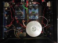
Hi all and a merry Christmas to you. I've just finished an F6 taking a couple of deviations along the road and a couple of extra months to get some new devices freshly filled with smoke.
Anyway the F6 is a lovely amplifier having an F5 and M2 to compare it with I find the F5 a bit harsh and the M2 a bit mellow but he F6 is perfect and seems to have some magic around the music which gives me a fresh sense of excitement listening to my old favorites. I comes out trumps against everything I've heard so far in this old life, I would definitely recommend it as a build to anyone looking at the Pass DIY projects.
Attachments
Steve Duffy,
Merry Christmas! And congratulations on completing your build!
You mention a couple of deviations and new devices - you mean mods to the "standard" F6? If yes, it would be interesting to know.
What are the voltage rails and the bias points that you've settled for? What speakers are you using?
Merry Christmas! And congratulations on completing your build!
You mention a couple of deviations and new devices - you mean mods to the "standard" F6? If yes, it would be interesting to know.
What are the voltage rails and the bias points that you've settled for? What speakers are you using?
I recently enjoyed listening to my hot-rod F6 again after being away for the holiday. Rail voltage is +/– 26.4V, output devices are FQH44N10, quiescent current presently set at 1.65 Amps. Input stage is a diamond buffer variant which has been discussed in the M2x thread. The PSU is, well, special; I've described it in the other F6 Amplifier thread.
Anyway, this amp has serious impact. The recent addition of the extra 24,000 uF caps to the outputs of the capacitance multipliers has made a world of difference. It has a different presentation from my Aleph J, which is really kinda nice, especially with hard rocking recordings. Sort of blows the doors off my M2x, which isn't really a fair comparison. The M2x is also special for what it does well. So both of N. Pass' signal transformer based amps are pretty amazing in their own way.
I have a recommendation from 2 Picodumbs to try out at some point, just as soon as I figure out a clean way to execute the modification. The hot-rod F6 could probably benefit from a touch more H2, but it has a firm grip on my old Vandersteens just as-is.
Last edited:
It has a different presentation from my Aleph J, which is really kinda nice, especially with hard rocking recordings.
TA,
Just double checking, you prefer the F6 on hard rocking recordings, or the Aleph J, which is very nice to listen to?
My F6 has a quality that I prefer on hard rocking recordings. The Vandersteen 2C speakers are both phase coherent and time-aligned. The F6 seems to have better control of these speakers, and the results are a lot of fun to listen to.
I did choose the output transistors and source resistor values with this in mind. The effort seems to have born fruit.
I did choose the output transistors and source resistor values with this in mind. The effort seems to have born fruit.
The PSU is, well, special; I've described it in the other F6 Amplifier thread.
Anyway, this amp has serious impact. The recent addition of the extra 24,000 uF caps to the outputs of the capacitance multipliers has made a world of difference. It has a different presentation from my Aleph J, which is really kinda nice, especially with hard rocking recordings. Sort of blows the doors off my M2x, which isn't really a fair comparison. The M2x is also special for what it does well. So both of N. Pass' signal transformer based amps are pretty amazing in their own way.
Nice work TA!
Sounds like your really enjoying your new addition 🙂
Since I’m using several SLB’s in various builds, I am interested in how you implemented the additional bulk capacitors. Can you post a picture? Thanks.
Best,
Vunce
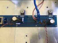
I don't have a picture with the extra caps yet, but the arrangement is simple enough:
The (4) Kemet screw terminal caps are wired into the positive, negative and ground spade lugs of the SLB boards, keeping channels separate. The negative speaker terminals are wired directly to the ground of their corresponding SLB board. Positive and negative power, plus ground, to the channel boards are connected to the SLB spade terminals. I left extra room for the bulk caps between the SLB boards and the rear panel of the chassis, thinking this arrangement would be beneficial.
The (4) Kemet screw terminal caps are wired into the positive, negative and ground spade lugs of the SLB boards, keeping channels separate. The negative speaker terminals are wired directly to the ground of their corresponding SLB board. Positive and negative power, plus ground, to the channel boards are connected to the SLB spade terminals. I left extra room for the bulk caps between the SLB boards and the rear panel of the chassis, thinking this arrangement would be beneficial.
Hi, I just built a standard F 6 with a couple ofl mistakes that. cost me the input JFETS and I needed to i stall the bigger diodes. . in stock form it" clearly a special amp. My speakers are home made open baffle bi-amped into the bass.
Last edited:
Steve,
Good to know that you sorted things out and the amp is playing music now. Indeed, the F6 is a fine amplifier, enjoy!
And thanks again to Mr. Pass for sharing the design with the DIY community. 🙂
Good to know that you sorted things out and the amp is playing music now. Indeed, the F6 is a fine amplifier, enjoy!
And thanks again to Mr. Pass for sharing the design with the DIY community. 🙂
Last edited:
Happy New year, guys
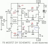
But I am not so happy and need help on my F6 adjusting bias. I don't know much about electronics, I measured both channels of the PSU, and I got positive and negative 25 Vdc. it should be correct. When I setting bias by measured across the R2 0.47 ohms. I got 2.1 mV and 4.7 mV for another channel at middle POT. I tried on one channel ,2.1 mV by turning P2 POT full span then voltage at R2 0.47 ohm can 2.3 mV at maximum only.
The Z1,2 were changed to LM329, Voltage across LM329 is 7.15 V
R7,8 are 3.6K.
At IRFP240 S to G voltage is about 80mV to 200 mV when turn P2 full span.
I found voltage across LM329 main voltage be dropped in R10 10K about 6.9 V. I don’t what to go next please give any advice. thank you in advance.
Attachments
if you have voltage across LM329 , and you have same voltage at both ends of 10K resistors , and there is no voltage at other side of secondaries , then xformer is Dodo
if you have voltage across LM329 , and you have same voltage at both ends of 10K resistors , and there is no voltage at other side of secondaries , then xformer is Dodo
voltage across R12 130 ohms is around 66 mV when 10K resistor has 4.9V so I calculated there is 0.5 mA there.
Please ...Zen mod
replace mosfets
as always , be sure that there is no contact with heatsink ( deburr holes!) , tightened enough , split washer
as always , be sure that there is no contact with heatsink ( deburr holes!) , tightened enough , split washer
replace mosfets
as always , be sure that there is no contact with heatsink ( deburr holes!) , tightened enough , split washer
Thank you. I normally do as you suggested.
It seems both channels need replacing.🙁
Before replacing anything you should better find out why the mosfet are dead , dont you think ?
usually stuff doesn't die without reason 😀
.
usually stuff doesn't die without reason 😀
.
Yes, I am thinking why.... and how to make sure whether others part still be okay before replacing.
Also another possible cause because it also has same symptom on POT P1 and Q1 at same channel.
Also another possible cause because it also has same symptom on POT P1 and Q1 at same channel.
- Home
- Amplifiers
- Pass Labs
- F6 Illustrated Build Guide