wondering if this pseudo wester electric is safe in case of the speaker - wire will touch the chassis '29V DC on the speaker  )
)
would it be more prudent to let the blocking cap at the output and wire the negative side of the speaker directly to source ?
)would it be more prudent to let the blocking cap at the output and wire the negative side of the speaker directly to source ?
An externally hosted image should be here but it was not working when we last tested it.

wondering if this pseudo wester electric is safe in case of the speaker - wire will touch the chassis '29V DC on the speaker
would it be more prudent to let the blocking cap at the output and wire the negative side of the speaker directly to source ?
[/IMG]
Isn't that different from any of the Son Of Zen type of amps. Also DC between ground and outputs.
You could put the cap in the other output line. That way DC source-to-ground is a lot lower. Will still kill your speakers, but with less smoke.
If you would tap between source and ground, you will make a different amp I think. You could even tap the output over the choke. Still need a cap though.
Then you'd still need a bypass cap on the source resistor to get back what little gain the amp has. And it would have to be enormous to get a full frequency response. That's two giant caps. It worked well but bugged me.You could put the cap in the other output line. That way DC source-to-ground is a lot lower. Will still kill your speakers, but with less smoke.
What led me down this path was that I wanted to use self bias (that's my preference in single ended tube amps), I realized that the speaker coil could "stand-in" for the primary of a tube output transformer and went through my notes on parafeed cap placement, trying all the alternatives.
This topology has been working great in the two amps I've built with it. In fact I'm visiting one of the amps today. I haven't seen or heard it in its current home. However it is very sensitive to speaker matching, more so than other amps I have built. Single drivers with no crossover definitely work best.
Then you'd still need a bypass cap on the source resistor to get back what little gain the amp has. And it would have to be enormous to get a full frequency response. That's two giant caps. It worked well but bugged me.
What led me down this path was that I wanted to use self bias (that's my preference in single ended tube amps), I realized that the speaker coil could "stand-in" for the primary of a tube output transformer and went through my notes on parafeed cap placement, trying all the alternatives.
This topology has been working great in the two amps I've built with it. In fact I'm visiting one of the amps today. I haven't seen or heard it in its current home. However it is very sensitive to speaker matching, more so than other amps I have built. Single drivers with no crossover definitely work best.
or letting the 4700uf to source to bypass the source resistor and put a 1000uf on the positive side , i love my altec
Wiring my monoblocks currently. I did successful resistor checks on the boards.
I will be mounting the boards on the heat sink with everything but the VFets, and continue the testing.
I am undecided as to whether I want to use a bench supply for testing, or the PSU I’m building for the amp. I want to be able to test the rather standard PSU before getting it hooked to the boards. With my previous amp I just hooked everything up, and biased the amp.
How would I test the PSU before hooking it up? I have some high wattage 8 ohm resistors as speaker substitutes, but I’m not sure of the actual amp impedance, or loading characteristics.
During the tests described in the article, are either the input or outputs shorted, or all open?
My mono lock amps PSUs involve 300VA toroids monolithic diode bridges (attached to the empty heat sinks on the case) and a CRC board with the standard values.
Am I just being too chicken? Just finish wiring and fire it up? (Sans VFET at first)
Don't short the outputs. You may short the inputs, but you don't have to.
8 Ohm with 28V across them will dissipate just shy of 100W, so...
You could use a light bulb as a load if you really want to test the PSU. Otherwise I'd just confirm that the PSU puts out an unloaded voltage fairly close to the nominal design voltage and confirm principal operation of the frontend circuit with the bench supply. After that, do the rest (frontend bias, output stage bias) with the actual PSU or the settings will be meaningless.
When I build mine, I used to test the PSU with 8ohm 50W resistors, but didn't quite get the voltage drop as is the case with the finished amp. I have dual PSU, like you are planning and got an additional +/- 2V drop. As for your second question, when testing voltages, as per test sheet, before installing the VFET's, nothing is shorted.
Last edited:
gain loss
Hi!
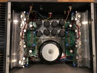
I up and running my vfet, it sounds very good.
But i missing gain it's huge different between my F5.
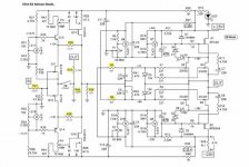
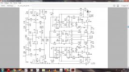
My build its based on Vfet r2 (teabag), the yellow is the diff, from the original.
I have the bias about 1,5 amp 54 celsius. The frontend is 1,8v.
The SW (feedback) is open, everything seems to be ok,
The problem is it decrease gain in the frontend.
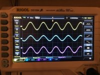
If you look at the picture from my oscilloscope.
The yellow is the input signal, 5,76 vrms, from the frontend (r20) 3,67 vrms.
What can the problem be?
hope someone can help me with this matter.
Hi!
I up and running my vfet, it sounds very good.
But i missing gain it's huge different between my F5.
My build its based on Vfet r2 (teabag), the yellow is the diff, from the original.
I have the bias about 1,5 amp 54 celsius. The frontend is 1,8v.
The SW (feedback) is open, everything seems to be ok,
The problem is it decrease gain in the frontend.
If you look at the picture from my oscilloscope.
The yellow is the input signal, 5,76 vrms, from the frontend (r20) 3,67 vrms.
What can the problem be?
hope someone can help me with this matter.
Attachments
Last edited:
The picture with your alternate values is to small to read properly, but it looks like you increase the resisters in yellow quite a bit. Surely that's going to attenuate the front-end. Maybe revert back to the orginal values would solve your problem.
The switch closed, what about R46, i cant find it on the pcb, maybe i missing something.
I don't think Mike put it on the board since Nelson removed it. I will look when i'm home and let you know.
Nice build by the way.
Thank's
I'm using the Toshiba parts 2sj313and 2sk313 .
I shall tried with the switch closed, maybe i must readjust the bias voltage to get the 1.8 volts across R25 and R26.
I got a two ways switch on the backside but did not check the voltage, maybe that is the
problem. I adjusted the 1.8 volts across R25 and R26 with open switch then i used the two ways switch to test the closed mode.
Last edited:
Gain should be 16dB in either case, see page 7 of the DIY Sony VFET pt2 article.
In regard to component values you should also check out post #2904 http://www.diyaudio.com/forums/pass-labs/276711-sony-vfet-amplifier-2-a-291.html#post5029632
In regard to component values you should also check out post #2904 http://www.diyaudio.com/forums/pass-labs/276711-sony-vfet-amplifier-2-a-291.html#post5029632
Thank's
My gain is not 16 db 1v in and 6,3v out.
I can see another value on the R23 in the Japanese Diy MJ Magazine,
R23 (2,2k) in my build is it 4,75k. First i'm going to try with the switch closed (Botte) readjust the bias and the 1.8 volts across R25 and R26.
My gain is not 16 db 1v in and 6,3v out.
I can see another value on the R23 in the Japanese Diy MJ Magazine,
R23 (2,2k) in my build is it 4,75k. First i'm going to try with the switch closed (Botte) readjust the bias and the 1.8 volts across R25 and R26.
Last edited:
- Home
- Amplifiers
- Pass Labs
- Sony VFET Amplifier Part 2