But it depends of course on how sophisticated your MOSFET model is.
The Exicon models are not particularly sophisticated.
They tend to underestimate H3.
Patrick
The Exicon models are not particularly sophisticated.
They tend to underestimate H3.
Patrick
But it depends of course on how sophisticated your MOSFET model is.
The Exicon models are not particularly sophisticated.
They tend to underestimate H3.
Patrick
By Exicon models do you mean the ones generated by Ian Hegglun?
Forgot where they were from. But Level 3.
No point to dwell on this.
It is only a tool to check things out.
Not to be believed 100%
Building is always reality.
Patrick
No point to dwell on this.
It is only a tool to check things out.
Not to be believed 100%
Building is always reality.
Patrick
By Exicon models do you mean the ones generated by Ian Hegglun?
I had been using Ian's parameters for laterals. Look at this post from last year:
Better power MOSFET models in LTSpice
These are the best I could find, although I posted elsewhere about my concern that the Ciss values are the same for N-channel and P-channel parts, which is not the case when biased to ~1 Amp. The P-channel capacitance becomes about double the N-channel when biased to that level, at least looking at the Exicon curves on the datasheets.
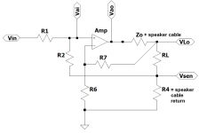
What do you gain by running 4 wires (2 additional sensing wires) to the speakers ?
IMHO nothing.
Cheers,
Patrick
IMHO nothing.
Cheers,
Patrick
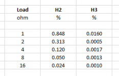
Something more interesting, for me at least.
First table shows distortion vs load, at constant 1W 1kHz.
i.e. how the amp behaves for different nominal speaker impedance.
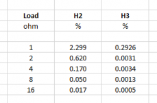
Second table shows distortion vs load, at constant +/-4W 1kHz.
i.e. how the amp behaves for a certain speaker with a varying impedance.
Patrick
.
First table shows distortion vs load, at constant 1W 1kHz.
i.e. how the amp behaves for different nominal speaker impedance.
Second table shows distortion vs load, at constant +/-4W 1kHz.
i.e. how the amp behaves for a certain speaker with a varying impedance.
Patrick
.
Attachments
What do you gain by running 4 wires (2 additional sensing wires) to the speakers ?
IMHO nothing.
Cheers,
Patrick
Would you say the same applies to the super regulator?
If you wish to have an amplifier which keeps the voltage at the speaker chassis at 100% what it should be, then yes.
But then I question whether the F7 is the right choice.
And then you can go further and measure the output voltage at chassis itself.
Without the internal (usually thin) wiring, spade connectors, crossover PCBs, ..., etc in between.
Cheers,
Patrick
But then I question whether the F7 is the right choice.
And then you can go further and measure the output voltage at chassis itself.
Without the internal (usually thin) wiring, spade connectors, crossover PCBs, ..., etc in between.
Cheers,
Patrick
I had been using Ian's parameters for laterals. Look at this post from last year:
Better power MOSFET models in LTSpice
These are the best I could find, although I posted elsewhere about my concern that the Ciss values are the same for N-channel and P-channel parts, which is not the case when biased to ~1 Amp. The P-channel capacitance becomes about double the N-channel when biased to that level, at least looking at the Exicon curves on the datasheets.
Here is a copy of 2 of his mosfets,I looked at the last year post and I guess he made a mistake which has been corrected here.I use these models and they are very good.
.model 10P20-75 VDMOS (pchan Rg=60 Vto={-0.535+1.7m*50} Rs={0.37*(1+3.4m*50)} Kp={0.995/(1+6.7m*50)} Rd=0.2 Ksubthres={0.12*(1+3.1m*50)} Mtriode=0.4 Lambda=5m Cgdmax=215p Cgdmin=10p a=0.25 Cgs=900p Cjo=1200p m=0.7 VJ=2.5 IS=4.0E-6 N=2.4 mfg=IH151206)
.model 10N20-75 VDMOS (Rg=60 Vto={0.17-1.6m*50} Lambda=3m Rs={0.245*(1+2.6m*50)} Kp={1.30/(1+8.3m*50)} Ksubthres={0.095*(1+2.9m*50)} Mtriode=0.3 Rd={0.6*(1+3m*50)} Cgdmax=100p Cgdmin=5p a=0.25 Cgs=600p Cjo=1100p
Last edited:
consider yourself lucky if you buy everything for that amp for less than 600$
No ****! I spent well over $1000 building my F4 and in retrospect I'm happy I did, though I was annoyed with myself for a while. I made a variety of dumb rookie mistakes and I spent at least $50 on shipping alone because of multiple orders from Mouser.
Then I spent yet more money on AoE and the Lab manual and an o'scope, function generator and power supply. Slowly working through the lab manual . . . Thankfully my wife is cool with my crazy learning experience.
Again, muchas gracias to Nelson for his wisdom and generosity.
Last edited:
Here is a copy of 2 of his mosfets,I looked at the last year post and I guess he made a mistake which has been corrected here.I use these models and they are very good.
.model 10P20-75 VDMOS (pchan Rg=60 Vto={-0.535+1.7m*50} Rs={0.37*(1+3.4m*50)} Kp={0.995/(1+6.7m*50)} Rd=0.2 Ksubthres={0.12*(1+3.1m*50)} Mtriode=0.4 Lambda=5m Cgdmax=215p Cgdmin=10p a=0.25 Cgs=900p Cjo=1200p m=0.7 VJ=2.5 IS=4.0E-6 N=2.4 mfg=IH151206)
.model 10N20-75 VDMOS (Rg=60 Vto={0.17-1.6m*50} Lambda=3m Rs={0.245*(1+2.6m*50)} Kp={1.30/(1+8.3m*50)} Ksubthres={0.095*(1+2.9m*50)} Mtriode=0.3 Rd={0.6*(1+3m*50)} Cgdmax=100p Cgdmin=5p a=0.25 Cgs=600p Cjo=1100p
Those look good - I'll give them a go - where did you find them?
What do you gain by running 4 wires (2 additional sensing wires) to the speakers ?
IMHO nothing.
Cheers,
Patrick
Its called a Kelvin connection. If you use such a connection, you eliminate the voltage drop along the current-carrying wires, therefore the measurement at the load is more accurate. Widely used in instrumentation applications and has been employed in some amplifier designs of the past. That said, the load current of a 20 Watt amp is pretty small, so the voltage drop caused by speaker cables is less than say, a 100 Watt amp driving a 4 Ohm load.
This probably veers in to the endless discussions about speaker cables which is not the point of this thread.
Thanks you for your explanation.
I knew about Kelvin connection about 15 years ago.
I still do not understand why it is important to have it between the terminals of an audio amplifier and a loudspeaker.
So maybe you can explain.
😀
Patrick
I knew about Kelvin connection about 15 years ago.
I still do not understand why it is important to have it between the terminals of an audio amplifier and a loudspeaker.
So maybe you can explain.
😀
Patrick
Those look good - I'll give them a go - where did you find them?
https://www.diyaudio.com/forums/sof...wer-mosfet-models-ltspice-12.html#post4544654
Now I am puzzled - those predate the models I referenced by 4 years (same thread), so I am not sure which are more accurate?
Perhaps @keantoken or @IanHegglun can chime in here....
Now I am puzzled - those predate the models I referenced by 4 years (same thread), so I am not sure which are more accurate?
Perhaps @keantoken or @IanHegglun can chime in here....
Keantoken says in his post that he would post the corrected models which are the ones I posted here.The models with the same capacitances are the wrong ones.
Hi
I have the same models as you Oreo, but my
.model 10N20-75 has; "m=0.7 VJ=2.5 IS=4.0E-6 N=2.4 mfg=IH151206" at the end the same as the .model 10P20-75.
Does anyone know if this makes a difference or not.
I have the same models as you Oreo, but my
.model 10N20-75 has; "m=0.7 VJ=2.5 IS=4.0E-6 N=2.4 mfg=IH151206" at the end the same as the .model 10P20-75.
Does anyone know if this makes a difference or not.
Thanks you for your explanation.
I knew about Kelvin connection about 15 years ago.
I still do not understand why it is important to have it between the terminals of an audio amplifier and a loudspeaker.
So maybe you can explain.
😀
Patrick
You might find this AES paper informative:
AES Engineering Briefs Forum >> Engineered Remote-Sensing Audio Power Amplifier for High-Fidelity Applications
- Home
- Amplifiers
- Pass Labs
- First Watt F7 review