This seams to be the most appropriate place for a feedback off topic.
I'm not sure how to class it, what is it apart from useless unless your speaker is a constant impedance (it's not a practical circuit - obvious problems, only an academic question).
Thought it might be useful for FR or active if you tweaked the active crossover.
I'm not sure how to class it, what is it apart from useless unless your speaker is a constant impedance (it's not a practical circuit - obvious problems, only an academic question).
Thought it might be useful for FR or active if you tweaked the active crossover.
Attachments
Last edited:
Thank you for the conformation sir, it looks like something to play with, I think I'm a couple of decades behind you.
Mysterious Df comparisons
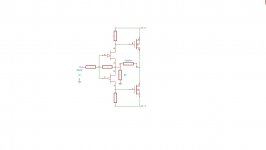
Finally mastered the exact values which work with my random transistor selection.
0.375R provides me with a Df in the range of 50, while 0.42R pushes it above 100.
It seems easy to make this switchable as different speakers have distinct preferences. Neither of my 2 pairs seem to enjoy particularly the high Df setting, the Wilsons WP7 sound horrible irrespective of Df, but the old ProAcs EBF are quite listenable at Df=50.
So, a reasonable question is how do they play when the pcf is switched off and Df=5. Strangely, the sound is unexpectedly bad, with practically no bass whatsoever. Why strangely? Because the same speakers play fantastically well with a valve push pull amp having a Df=3, with no trace of the anemic bass and gutless dynamics.
Perhaps the pcf modifies more of the amp behaviour than merely Df. Ideas?
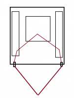
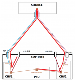
I would like to ask about grounding a current feedback topology when using a common PSU for a stereo amplifier.
Because of the current sensing resistor the Power (Speaker Returning) GND is on the amplifier PCB connected directly to the Signal GND.
In this case I'll have a ground loop, like attached on the 1st picture, right?
(The red line is the Signal GND via the Left-RCA - Left-Amp - Common PSU - Right AMP - Right-RCA circuit)
Will this cause hum problems?
Should I use some different grounding layout like on the 2nd picture?
Or maybe putting a "Hum Breaking Resistor" between the Signal GND and the Power GND on each channel like explaned here on the 33rd page?
Thanks!
Attachments
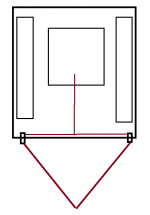
The one on the left gives more opportunity for the power transformer to
induce ground current through that red loop, being that the loop is closer to
where I imagine the transformer will be.
induce ground current through that red loop, being that the loop is closer to
where I imagine the transformer will be.
So there is a ground loop with the left version, right?
And in this case the same is true for this F7 layout (link) as well?
Because the RCA GNDs are connected via the green Power GND wires
through the PS PCB, as attached and marked with the orange loop, right?
Shouldn't this layout be avoided somehow?
And in this case the same is true for this F7 layout (link) as well?
Because the RCA GNDs are connected via the green Power GND wires
through the PS PCB, as attached and marked with the orange loop, right?
Shouldn't this layout be avoided somehow?
Attachments

I think your forgetting about the 'ground loop breaker' - the CL60 connection between 0V and safety earth.
And i think you misunderstand the issue under discussion, which is not related to the presence or absence of a safety earth.
There is a wire level "0 ohm" GND loop without involving the safety earth at all via the PS GND, isn't it?
So there is a ground loop with the left version, right?
And in this case the same is true for this F7 layout (link) as well?
Because the RCA GNDs are connected via the green Power GND wires
through the PS PCB, as attached and marked with the orange loop, right?
Shouldn't this layout be avoided somehow?
The rca connectors + and - are isolated from the chassis in my build and I think most of them (bought mine from digikey ).The - of those rca's goes to the common star point of the +/- supply (common point of the last capacitors in the supply,NOT the first capacitors after the rectifiers),this is the same point for all your boards "grounds".I use quotation marks as this is not the true ac power ground that is connected to your power cord.This common point is then brought back to the true ac ground thru a cl60 thermistor in my build.Mr.Pass has a good schematic diagram of the power supply arrangement in one of his first watt website articles.
Again lets put the safety earth and the metal case completely aside.
Let's assume an open desk version on a wood plate. ;-)
The input RCA GNDs are already tied together at the source (preamp),
and then secondly inside the amplifier at the PS GND and so there is a GND loop as I see.
Let's assume an open desk version on a wood plate. ;-)
The input RCA GNDs are already tied together at the source (preamp),
and then secondly inside the amplifier at the PS GND and so there is a GND loop as I see.
The L & R input 0V's are in parallel (in most circumstances), hence your loop, isn't that effectively the same as a Litz or an oxidised multi-strand cable? 
If it's not causing an issue, don't worry.
If it's not causing an issue, don't worry.
Last edited:
(For me) there are 2 different types of joy regarding electronics:
1) got it working
2) understand why it works... 🙂
I draw a picture trying to explain my current level of knowledge about this layout.
Am I missing something? If not, why this isn't humming by default?
1) got it working
2) understand why it works... 🙂
I draw a picture trying to explain my current level of knowledge about this layout.
Am I missing something? If not, why this isn't humming by default?
Attachments
Papa already gave the answer, there is more to it than the loop (the rabbit hole is quite deep).
You already have the knowledge to answer your own question.
If you powered the circuit from a battery, would you expect hum - no, there are no AC fields to pick up.
How does a transformer work, wire wrapped around a lump of iron, placing wire (// to the winding) close to the transformer will induce a current, rotate the wire to to cut the magnetic field at exactly 90° the pickup will reduce to 0.
The wiring is therefore susceptible to pickup, this can be negated to a degree by proper layout, run +/_ supplies together, using twisted wires on the input; If there is pickup on one wire, it will be equally induced onto the other wire - effectively cancelling and keeping the differential the same.
Bearing the above in mind, placing wiring in an inadvertent loop around the transformer is asking for trouble, move one of the signal lines to the other side to run // with the other channel will collapse the loop and reduce pickup.
GND loop is not only causing trouble when winded to the trafo directly.
In this position with this area it usually causes trouble.
Cancelling is also working on balaned inputs with symetrical wires but
now the impedances for the GND and "hot" signals are different.
So the question still stands for me...
In this position with this area it usually causes trouble.
Cancelling is also working on balaned inputs with symetrical wires but
now the impedances for the GND and "hot" signals are different.
So the question still stands for me...
So no one could explain me why this GND loop doesn't cause any hum in an F7?
Because in theory this loop should be breaked as explained here on the 33rd page?
Because in theory this loop should be breaked as explained here on the 33rd page?
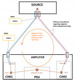
To be honest I'm still confused about this "looped" common RCA + PS
GND layout regarding both hum + common impedance coupling.
I just draw a 2nd image with the same layout showing a possible current path (RED line) via the signal GND loop:
Any thoughts on that..?
GND layout regarding both hum + common impedance coupling.
I just draw a 2nd image with the same layout showing a possible current path (RED line) via the signal GND loop:
- let's assume there is a large output current impulse on channel #1
- it goes out to the LS and comes back via the LS #1 GND "port"
- then most of it goes of course to the common PS GND via the CH#1 P-GND wire
- but because of the impedance of this wire ("loaded" with the actual output current)
- if there is no current at the moment on channel #2
- a certain current can flow through the signal GND loop the other channels GND
- in this case this current will modulate/distort the original signal
- and in a special way because it's amplitude depends on the difference of the actual output currents of the 2 channels
Any thoughts on that..?
Attachments
Last edited:
- Home
- Amplifiers
- Pass Labs
- First Watt F7 review