Thanks for your explanarion Claas.
I had a look with the scope at the output from my old usb soundcard using the signal generator included in REW that I downloaded. On the scope it looks like a sine wave but not perfect and not as smooth as I had liked. I assume the old soundcard is not that great.
I then tried playing a 1kHz sine from a test cd I had ripped but the output from my 16 bit squeezebox classic was not that good either.
The new Focusrite 2i2 I bought for testing does not work on my old workshop test pc that runs XP. Arrgh!
So, I hoped to get some work done today but everything I touched went wrong. I even managed to get a cable stuck around my wheelchair and had to call someone to free me :-(
Tomorrow is another day. I hope to get the scope hooked up and do some testing.
Don't give up !
In the past, I used my old (bought used) little Tektronix signal generator. My Rigol scope using its FFT function showed about -40 dB second harmonic distortion on my 2A3 SET amps. So I thought - maybe that's the distortion of the tube amps ...
Distortion spectra for my M2 amps were similarly in the - 40 dB range ... hmm ... maybe the FFT that's built into the Rigol doesn't have higher resolution ?
When I used the Focusrite 2i2 I got, I measured distortion easily down to -80 dB and lower for the M2. So I found out, my old Tektronix signal generator did have harmonics in the -40 dB range for a 1 kHz sine wave ...
What did I draw from this ?
- the not-very-good signal generator still shows a very clean sine wave and very clean rectangle on the scope. It also proved perfectly adequate for oscillation hunting.
- the Focusrite 2i2 does not only have a very good ADC for measuring, but also a very low-distortion DAC / signal generator. I think it would pay off to make work in your system.
For oscillation measurement, you don't need a very good signal generator. The output from your Squeezebox should work for a 1 kHz sine wave. If you get a very un-clean signal, chances are that you have noise or bad connections somewhere between Squeezebox and scope.
You can also start by looking for signs of oscillation on the pre-amp output without a signal input; inputs of the preamp grounded, scope probe to the output and scanning through the frequency range ... in my case with the Sony amp, oscillation shows without a signal ...
Best of luck,
Claas
Things are getting weird. Remember that the amp works and sounds fine (although I admit I only tested it on some cheap speakers so far).
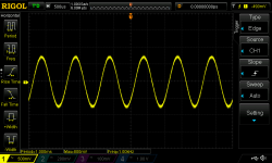
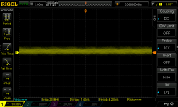
I attached the Focusrite 2i2 balanced to the amp input and generated a 1 kHz sine wave. I attached a Rigol probe to one of the inputs (+ or -). The amplifier was turned off and I got this on the scope
DS1Z_QuickPrint1.png
It is not perfect, but it is as I expected a 1 kHz sine wave.
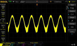
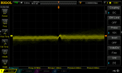
I then switched the amplifier on and the scope screen changed to
DS1Z_QuickPrint2.png
Where did the fuzziness come from?
I interpret that the input is somehow changed by switching on the amplifier. I assume this should not happen. What could cause this?
To make sure the input circuitry is correct, I have taken high-res photo's to check all resistor values (at the time I bent the leads so that the value could be read after soldering). Everything (all resistors on the board) check out. All resistors are Dale that I bought from Mouser or Digikey and I am pretty sure I checked every one of them before soldering because I tried to match them as close as possible.
I also tried to get some idea of the distortion but the results are so strange that I cannot interpret them. Changing the fft parameter from 64k to 16k had a huge effect on the fft analysis, with dominance of k2/k3 reversed! I expected that changing parameters would affect the results, but had not expected such a fundamental difference. Or could this be due to a problem in the amp? Is there a preferred set of parameters to use?
Thanks,
Albert
More confused than before I started testing
I attached the Focusrite 2i2 balanced to the amp input and generated a 1 kHz sine wave. I attached a Rigol probe to one of the inputs (+ or -). The amplifier was turned off and I got this on the scope
DS1Z_QuickPrint1.png
It is not perfect, but it is as I expected a 1 kHz sine wave.
I then switched the amplifier on and the scope screen changed to
DS1Z_QuickPrint2.png
Where did the fuzziness come from?
I interpret that the input is somehow changed by switching on the amplifier. I assume this should not happen. What could cause this?
To make sure the input circuitry is correct, I have taken high-res photo's to check all resistor values (at the time I bent the leads so that the value could be read after soldering
). Everything (all resistors on the board) check out. All resistors are Dale that I bought from Mouser or Digikey and I am pretty sure I checked every one of them before soldering because I tried to match them as close as possible.I also tried to get some idea of the distortion but the results are so strange that I cannot interpret them. Changing the fft parameter from 64k to 16k had a huge effect on the fft analysis, with dominance of k2/k3 reversed! I expected that changing parameters would affect the results, but had not expected such a fundamental difference. Or could this be due to a problem in the amp? Is there a preferred set of parameters to use?
Thanks,
Albert
More confused than before I started testing
Attachments
For a start you should not be concerned about the FFT spectrum when doing basic functional testing. It will be much easier if you just leave that feature turned off for now. What immediately comes to mind when looking at the input waveforms is where do you have the scope probe ground lead connected and also how are you connecting the balanced input signal to the 1.7 board. If the focusrite is truly balanced you only need to connect the + and - signals - (Pin 2 and 3 on an xlr connector) You do not need pin 1 at all. If however, like some low priced balanced pro audio gear, the output of the focusrite is not truly balanced then you need to connect pin 1 to the 1.7 to get a quasi balanced signal.
If you connect your scope probe directly across the output of the focusrite with the 1.7 disconnected what does the waveform look like?
What does the 1.7 output look like on the scope with the input signals you are measuring above. Measure each phase of balanced output with respect to the circuit ground.
Hi Brian,
The Focusrite 2i2 is supposed to be balanced.
Scarlett 2i2 | Focusrite
I assumed it would be properly balanced and had not thought about the possibility that it was not.
I connected one line output of the 2i2 to an XLR jack on the back panel. It is connected directly to IN+, IN- and GND on the AP1.7 board (no input selection switch involved). The probe was connected to one of the inputs (can't remember if it was + or -) and GND at the same point on the AP1.7 board.
Tomorrow I will see what happens when I disconnect pin 1 (GND) from the XLR jack to the Ap1.7 board (thus running only + and - from 2i2 to AP1.7).
I will also try running + and GND (grounding - on the AP1.7 board) and will measure 2i2 output unconnected to AP1.7.
I did have a look at the output. The output of the AP1.7 looked reasonable. Not as good as the first sine, but not as bad as the second either. There was a differences in amplitude of the + and - outputs. If I remember corrrectly about 10% at about 700mV output (note that output is measured after onboard volume relays, with volume at about mid-level) which seemed much too high.
I did not notice the imbalance when I listened to the amp because it was connected single ended to a DIY F4. It sounded OK on cheap old speakers.
Thanks and I will report back.
Albert
Some interesting measurements today!
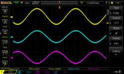
1000Hz sine wave, -3dBFS, REW signal generator through Focusrite 2i2.
No difference whether laptop was powered by battery or AC.
2i2 to Rigol, probe connected at pins 1 and 3 of 3m XLR cable. No connection to amplifier.
DS1Z_QuickPrint3.png
Noise (5 ns horizontal division)
DS1Z_QuickPrint5.png
For comparison, Rigol probe shorted. Same 5 ns horizontal division.
DS1Z_QuickPrint6.png
Is the XLR cable noisy? Probe connected directly to 2i2 to eliminate cable. Same output.
DS1Z_QuickPrint7.png
Same but using different time/division (100 us).
DS1Z_QuickPrint8.png
2i2 seems to have proper balanced output. Images of pins 1+2 and 1+3 look the same. Output of pins 2+3 looks the same but double the amplitude of 1+2 or 1+3.
Next the AP1.7 meaurements.
Attachments
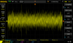
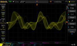
AP1.7 left channel. Volume at max.
Input + and input - connected to GND.
Rigol probe (yellow) to input + and GND.
DS1Z_QuickPrint34.png
DS1Z_QuickPrint25.png
WTF???
Rigol probe (blue) to output + and GND.
DS1Z_QuickPrint28.png
DS1Z_QuickPrint33.png
Rigol probe (pink) to output - and GND.
DS1Z_QuickPrint22.png
DS1Z_QuickPrint32.png
Just to reiterate, inputs grounded. And the amp sounds fine?!?
Attachments
I had been thinking before that it seemed as if the input (measured at the input!) was distorted by the amp circuit. I had checked all resistor values between the input and the active part of the circuit and found nothing wrong (or any other resistor for that matter). Then I realised that I had listened to the amp connected to a diy F4 and had set the amp for maximum gain, including bypassing the 10k input resistor.
aleph-17 switches.gif
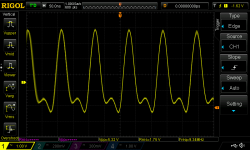
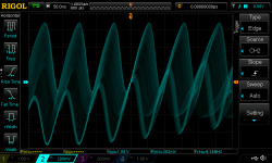
After switching the 10k back into the circuit, the shorted input looked a lot better!
DS1Z_QuickPrint35.png
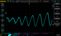
The outputs with shorted inputs looked better too!
DS1Z_QuickPrint36.png
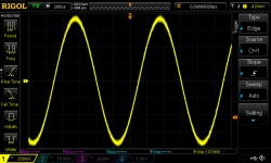
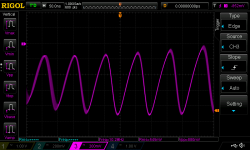
So, back to the signal generator. 1000Hz sine wave as before. This is what the input and output look like with the 10k resistors in the circuit.
DS1Z_QuickPrint40.png
I tested the other channel as well and it is also fine.
What did I learn? Well, besides a lot about my scope and other test and measuring equipment an important lesson was to trust my ears because the amp sounded ok.
aleph-17 switches.gif
After switching the 10k back into the circuit, the shorted input looked a lot better!
DS1Z_QuickPrint35.png
The outputs with shorted inputs looked better too!
DS1Z_QuickPrint36.png
So, back to the signal generator. 1000Hz sine wave as before. This is what the input and output look like with the 10k resistors in the circuit.
DS1Z_QuickPrint40.png
I tested the other channel as well and it is also fine.
What did I learn? Well, besides a lot about my scope and other test and measuring equipment an important lesson was to trust my ears because the amp sounded ok.
Attachments
With regard to #547:
That looks like oscillation to me ...
Inputs grounded, no signal in, right ?
The amp could still sound OK because the 400-500 mV of multi-MHz oscillation is just riding on top of the audio signal. But it is an additional stress on the amp and the components, and maybe on devices downstream.
Now, the interesting question: how to tame the oscillation ? Here the people who have experience with this circuit need to chime in ...
With regard to #548:
That looks good !
What I don't understand at the moment: Why was the amplifier oscillating with the 10k Ohm resistors bypassed but the inputs shorted to ground ?
Best regards,
Claas
Last edited:
With regard to #548:
That looks good !
What I don't understand at the moment: Why was the amplifier oscillating with the 10k Ohm resistors bypassed but the inputs shorted to ground ?
Best regards,
Claas
Hi Claas,
I don't understand it either. As a guess I think that the oscillation originates at the gain 610's but that is mainly because they are closest (their gates connect to the input through the 10k resistors). Could be something else entirely haha.
If I understand the user manual correctly, bypassing the 10k resistor is the default setting.
What I find interesting is that the user manual does not specify that the input impedance is changed (which I assume it is) by the switch.
More measuring I think to see if I can locate the source of the oscillation. No idea what I am looking for but that should not deter me.
Albert
In post 547 it looks like you have an oscillation. If you can duplicate those conditions again and see the same behaviour, have a look at the power supply to see if it is clean or showing oscillations as well. One thing you can do to help prevent oscillation in the current sources is to increase the value of the base or gate stopper resistors. I think I changed mine from 220 to 470ohms. Which circuit board version are you using?
I've been reading through most of this thread, as I have a set of reliable borads that I made almost 15 years ago. Other things happened in life, and the boards have been sitting in a drawer up unitl now.The boards are OK and easily solderable even after these years, as they were originally chemically tin plated.
But - my question concerns remote control. I dropped out of programming 30 years ago, abd have not kept up with modern controllers and programming systems.
Has anybody looked into a control processor that will fit with the original design?
But - my question concerns remote control. I dropped out of programming 30 years ago, abd have not kept up with modern controllers and programming systems.
Has anybody looked into a control processor that will fit with the original design?
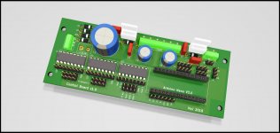
The board I used was given to me by a diy audio member and resembles the volume control of the original design, but it only uses 7 relays instead of 8. It is designed to use a pot and an adc chip to control the relays. I decided not to use the pot and adc but control the relays directly from an arduino based control board.But - my question concerns remote control. I dropped out of programming 30 years ago, abd have not kept up with modern controllers and programming systems.
Has anybody looked into a control processor that will fit with the original design?
besteld 1.jpg
The control board has 8 separate left and right volume bits that can be switched on and off. I take the output of a shiftregister (on the control board) to drive the relays on my AP1.7 board (instead of the pot and adc). It was simple enough to design the software so it can work with either 7 or 8 bits.
I use it with IR remote control and a 16x2 display. The board is designed so that perhaps in the future I could use rotary encoders, but for now just IR remote is all I need.
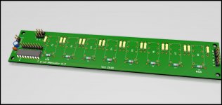
I have also made a volume board that follows the AP1.7 original design.
3d 1.jpg
It will (eventually) replace the Dantimax boards I had been using in an AP1.7 a friend of mine built using KK boards.
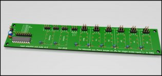
Finally, I made an input selection, tape monitor and output mute board. It is also controlled by the control board above. It can be used for single ended stereo or balanced mono.
3d view.jpg
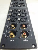
I use a mix of rca and xlr jacks on my rear panel.
WhatsApp Image 2019-01-25 at 15.54.15.jpeg
When using single ended inputs you should ground the IN- (in the above example for inputs 4 and 5). I am not sure how the Dantimax boards do this, but I designed the board so it could be used with any mix of rca and xlr connectors and simply install a jumper for rca inputs (grounding IN-).
Note that this was my first attempt at designing boards and working with arduino's and I am still debugging my amp haha.
I would recommend you download the arduino development software at www.arduino.cc (free!) and order a simple arduino uno at aliexpress (or ebay or whatever is convenient) for a couple of €. https://www.aliexpress.com/item/hig...-Arduino-UNO-R3-NO-USB-CABLE/32697443734.html and You can follow the many tutorials and examples on the web.
The arduino uno uses a ATmega328P 16MHz 8 bit processor with 32kB program memory and 2kB or sram. Plenty for this type of stuff.
Attachments
I am heading to the shed to start measuring!In post 547 it looks like you have an oscillation. If you can duplicate those conditions again and see the same behaviour, have a look at the power supply to see if it is clean or showing oscillations as well. One thing you can do to help prevent oscillation in the current sources is to increase the value of the base or gate stopper resistors. I think I changed mine from 220 to 470ohms.
The board was given to me by a diy audio member who had had it for years but never used it. I do not know where it came from but I think it looks the same as this one I found on ebay. SE MOSFET full balanced +128 step volume control PCB ! | eBayWhich circuit board version are you using?
Hi Gerd! Still hunting for my oscillation!
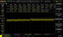
I made some more measurements today. Following Brian's suggestion I had a look at the output of the powersupply.
There is noise (a noisy, rough sine wave at somewhere between 30 and 40 MHz; not shown) and it is larger on the amp side of the 3R3 resistor that connects it to the PSU than at the PSU side. Assuming the 3R3 resistor attenuates the noise, I conclude that the noise originates from the amp and not the PSU. This seems to agree with the fact that the oscillation is affected by the 10k input signal resistor.
What bothers me about the oscillation that I see at the input is that it not a clean sine wave. I assume it is the result of the original sine osciallation interacting with the circuit.

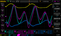
I put my probes across the 680pF capacitor that sits across the ZTX550.

Again, the PSU side (CH2) is smaller than CH3 (same 50mV scale)
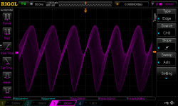
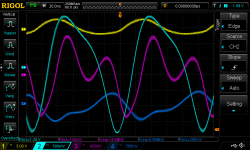
Leaving the CH3 probe in the same spot, I moved the CH2 probe to the 2k trimpot (in my case a direct 0R connection because I wanted maximum gain). Note that CH2 is now on a 500mv scale and CH3 is on 100mV.

When I disconnected the link between the + and - side of the amps (removed my wire in the spot of the 2k trimpot) the screen only changed marginally. Nor did it change when I moved the CH2 probe from the + side to the unconnected - side of the disconnected 0R resistor that sits in place of the 2k trimpot.
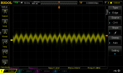
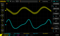
What happens when I measure the source and drain of the middle/gain irf610?
CH1 connected between 10uF and irf610. CH2 connected at connection between the 2 irf610's.

I note that CH1 shows a relatively smooth sine wave.
Back to my original observation that the osciallation is much greater when the 10k source resistor is bypassed. The input is connected to the gate of the gain irf610 (via 10uF and 221R in series). It is also connected the ccs irf9610 and gain irf610, but this is via a 221k resistor so I assume that the extra 10k that is bypassed (or not) would not have such a large effect.
Based on this I hope the gain irf610 is the culprit. I intend replacing the gatestopper by a larger value (470? 680?) to see what happens. Problem is I will have to remove the board from the case, unsolder the 221R's in there, etc.
I would appreciate any suggestions.
Thanks,
Albert
I made some more measurements today. Following Brian's suggestion I had a look at the output of the powersupply.
There is noise (a noisy, rough sine wave at somewhere between 30 and 40 MHz; not shown) and it is larger on the amp side of the 3R3 resistor that connects it to the PSU than at the PSU side. Assuming the 3R3 resistor attenuates the noise, I conclude that the noise originates from the amp and not the PSU. This seems to agree with the fact that the oscillation is affected by the 10k input signal resistor.
What bothers me about the oscillation that I see at the input is that it not a clean sine wave. I assume it is the result of the original sine osciallation interacting with the circuit.
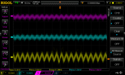
I put my probes across the 680pF capacitor that sits across the ZTX550.
Again, the PSU side (CH2) is smaller than CH3 (same 50mV scale)
Leaving the CH3 probe in the same spot, I moved the CH2 probe to the 2k trimpot (in my case a direct 0R connection because I wanted maximum gain). Note that CH2 is now on a 500mv scale and CH3 is on 100mV.
When I disconnected the link between the + and - side of the amps (removed my wire in the spot of the 2k trimpot) the screen only changed marginally. Nor did it change when I moved the CH2 probe from the + side to the unconnected - side of the disconnected 0R resistor that sits in place of the 2k trimpot.
What happens when I measure the source and drain of the middle/gain irf610?
CH1 connected between 10uF and irf610. CH2 connected at connection between the 2 irf610's.
I note that CH1 shows a relatively smooth sine wave.
Back to my original observation that the osciallation is much greater when the 10k source resistor is bypassed. The input is connected to the gate of the gain irf610 (via 10uF and 221R in series). It is also connected the ccs irf9610 and gain irf610, but this is via a 221k resistor so I assume that the extra 10k that is bypassed (or not) would not have such a large effect.
Based on this I hope the gain irf610 is the culprit. I intend replacing the gatestopper by a larger value (470? 680?) to see what happens. Problem is I will have to remove the board from the case, unsolder the 221R's in there, etc.
I would appreciate any suggestions.
Thanks,
Albert
Attachments
I remember a similar problem, I think I removed the Zener at the input.
Thanks for the tip. I will bypass the zener tomorrow and see if it makes a difference!
- Home
- Amplifiers
- Pass Labs
- Pass Aleph P 1.7 preamp builders thread