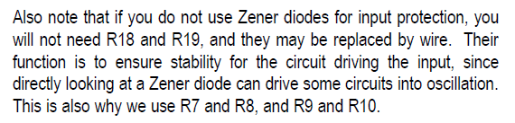
Yes. I plan to use a wire with 2 clips. One clip on the top zener lead, the other clip to GND. I hope the signal chooses the lead instead of the zeners 🙂
"Then I read somewhere about possible issues with the protection zeners on the input, high capacitance cables, resulting in stability issues on the source side, where even a little resistance on the input solves the problem. So I just swapped the 10k resistors for 1k. Clear sound and no issues.. Good enough for me. "
https://www.diyaudio.com/forums/pass-labs/208228-aleph-1-7-distortion-3.html#post2961813
https://www.diyaudio.com/forums/pass-labs/208228-aleph-1-7-distortion-3.html#post2961813
Yes. I plan to use a wire with 2 clips. One clip on the top zener lead, the other clip to GND. I hope the signal chooses the lead instead of the zeners 🙂
So you will send the input signal to GRD.
:--))
and now?
So you will send the input signal to GRD.
:--))
and now?
Thanks for the links above. Some more thimgs to consider!
Yes, the input to GND. Not a problem for testing because I was testing with shorted inputs anyway haha. If it solves the problem, I will remove the zeners before listening 🙂
By the way, I remember testing an Aleph H some years ago and got a lot of distortion when I removed the input resistor. Problem solved by adding an input resistor. No scope at the time, but makes me wonder ...
I am no EE and have no real experience with circuits other than building in a way that resembles painting by numbers 😀
Studying the schematic and trying to make sense of what I saw, I thought I could explain my measurements if the gain irf610 was the oscillating culprit, but was not sure.
After another day of measuring (and not really getting any closer) I decided to take the plunge and see if my observations had resulted in me drawing the correct conclusion. With the board still in the case, I used side cutters to cut the body of the 221R between the input 10uF and the gate of the gain irf610 (but leave something to connect a clip to). I then used some wires and clips and a 1k multiturn trimmer to see if a higher value gate stopper resistance would remove the oscillation.
It did! 😀
I was able to get the circuit oscillating again (and again, and again) by reducing the resistance. After I was finished playing around with it, I measured the resistance at which the oscillation was triggered. The trimmer was at 391R.
Next step will be to remove the board from the case and replace all 4 221R gate stopper resistors of the irf610 gain devices by higher values. I hope this fixes the problem once and for all!
Thanks for all your help and I hope to report in a few days or so how things went.
That’s great news!! Remember to test the pre at full operating temperature and with all possible input levels and frequencies it will likely see. This will give you confidence that you’ve quenched any oscillation issues.
I changed the 221R gate resistors of the irf610 gain devices to 620R. When the amp is warm there is no oscillation but when the amp is switched on from cold, the oscillation is there until the amp warms up.
According to What are MOSFETs? - MOSFET Parasitic Capacitance and Its Temperature Characteristic | Basic Knowledge | ROHM TECH WEB: Technical Information Site of Power Supply Design Ciss is not affected by temperature, so it is not the warming up per se.
Could the psu voltage (that slowly creeps up to a steady state, in my case today 61.04V) be the cause?
Interestingly, the oscillation is also visible when the amp is switched off (3 secs while the supply caps are drained).
https://www.diyaudio.com/forums/attachment.php?attachmentid=732208&stc=1&d=1548664868
I had a look at the psu voltage (after the 3R3 resistor). It rises slowly (slower than I had thought) and oscillation stopped when it reached 60.67V. Switching the amp off produces oscillation as soon as the voltage slowly drops below 60.67V.
Switching the amp on again while it is still warm again results in oscillation that stops as the voltage rises, but with a warm amp the oscillation stop at a much lower voltage (56V) than when cold.
So, it seems there is something going on that depends on both voltage and temperature.
More reading, thinking and measuring are in order!
Attachments

I don’t have a schematic here in front of me and it’s been a while since I worked on the 1.7 but in my case IIRC I had to increase the resistors in series with the base of the transistors used in the current sources to prevent oscillation. They serve the same basic function as the gate stopper resistors for the mosfets.
Thanks Brian. A good tip.
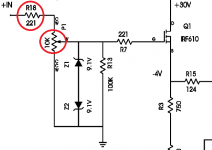
I read somewhere else that (as Gerd mentioned) the protective zeners at the input may lead to oscillation when there is no resistor between it and the input. Nelson mentions this in the Bosoz paper (and mentions the requirement of the input resistor) but seems to have left them out in the Aleph P1.7 schematic. Perhaps the Bosoz paper was written later (I did not check the dates).
Tomorrow I plan to remove the protective zeners to see what happens. If that does not do the trick, then I will have a look at the other gate stoppers and base resistors. Or perhaps add a small (100R?) Input resistor. The switchable 10k eliminated the oscillation but attenuated the signal too much.
I have not had a good look yet at the other channel. I changed the resistors but no decent measurements yet.
Oh, I did add a 1uF film cap across the zener stack in the power supply. Might smooth out a bit of the noise and should not do any harm.
Well, it looks like things were much more simple than they seemed ...
(Now we just hope that looks aren't deceiving 😀)
The oscillation did not occur with the 10k input resistor switched in circuit. Why did the 10k resistor have such an effect?
After reading the Bosoz paper (balanced zen linestage) http://www.firstwatt.com/pdf/art_bosoz.pdf I wondered about the input protection zeners that Gerd had mentioned. In the Bosoz paper a 221R resistor was recommended if the builder did not opt to use a 10k pot before the input because the protection zeners could cause oscillation. Now, for me 221R is low enough not to cause much attenuation, and (lucky for me) the same value I had just removed from the gates of the gain irf610 gain devices.
Rather than short IN+ and IN- direct to GND during testing, I inserted a 221R resistor between IN+ and GND and one between IN- and GND.
Result: On first inspection (without 10k input resistors!) there is NO oscillation, even when the amp is cold or when the amp is turned off.
Although the AP1.7 service manual I have is not dated, some of the schematics are dated 1995 and 1996, so I assume it was probably written in 1996.
The Bosoz circuit resembles a simplified AP1.7. The Bosoz paper mentions the input protection zeners as a possible cause of oscillation when used without input resistors. The Bosoz paper is dated 1997.
I will test further over the coming days to see if this has finally solved the problem and will report back.
If anyone runs into oscillation problems with an AP1.7 when run without the 10k input resistor, try a 221R resistor in series with the input. It may just solve the problem 😀
Well, it looks like things were much more simple than they seemed ...
(Now we just hope that looks aren't deceiving 😀)
The oscillation did not occur with the 10k input resistor switched in circuit. Why did the 10k resistor have such an effect?
After reading the Bosoz paper (balanced zen linestage) http://www.firstwatt.com/pdf/art_bosoz.pdf I wondered about the input protection zeners that Gerd had mentioned. In the Bosoz paper a 221R resistor was recommended if the builder did not opt to use a 10k pot before the input because the protection zeners could cause oscillation. Now, for me 221R is low enough not to cause much attenuation, and (lucky for me) the same value I had just removed from the gates of the gain irf610 gain devices.
Rather than short IN+ and IN- direct to GND during testing, I inserted a 221R resistor between IN+ and GND and one between IN- and GND.
Result: On first inspection (without 10k input resistors!) there is NO oscillation, even when the amp is cold or when the amp is turned off.
Although the AP1.7 service manual I have is not dated, some of the schematics are dated 1995 and 1996, so I assume it was probably written in 1996.
The Bosoz circuit resembles a simplified AP1.7. The Bosoz paper mentions the input protection zeners as a possible cause of oscillation when used without input resistors. The Bosoz paper is dated 1997.
I will test further over the coming days to see if this has finally solved the problem and will report back.
If anyone runs into oscillation problems with an AP1.7 when run without the 10k input resistor, try a 221R resistor in series with the input. It may just solve the problem 😀
From your description, you have placed the 221R resistors in parallel with the input and not in series. This almost shorts the inputs to ground. If your music source has a 10k output impedance, the resulting voltage divider will result in lots of dBs of loss at the input of the amplifier.
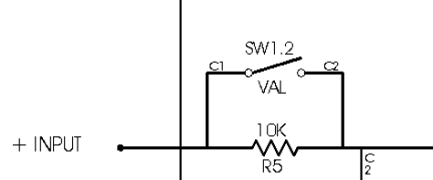
No, it really was in series. Perhaps the following diagram make it clear.From your description, you have placed the 221R resistors in parallel with the input and not in series. This almost shorts the inputs to ground. If your music source has a 10k output impedance, the resulting voltage divider will result in lots of dBs of loss at the input of the amplifier.
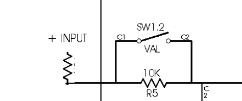
Original above. Modified below.
Attachments


No, it really was in series. Perhaps the following diagram make it clear.
Original above. Modified below.
You wrote this
Rather than short IN+ and IN- direct to GND during testing, I inserted a 221R resistor between IN+ and GND and one between IN- and GND.
Result: On first inspection (without 10k input resistors!) there is NO oscillation, even when the amp is cold or when the amp is turned off.
That is not what you have drawn unless you connected the floating input of the 221R resistor to ground which places the 221R resistor in parallel with the input of the amplifier.
I am sorry, but I do not get your point. Both schematics show a labelled, ungrounded input. The modified version has an extra input resistor (in series with the input).
I was testing with inputs shorted to ground. That is not shown on the schematic.
Normal shorting would mean IN+ to GND and IN- to GND.
I wrote:
So, instead of a wire from IN+ to GND there was now a resistor.I inserted a 221R resistor between IN+ and GND and one between IN- and GND.
To play music in the unmodified amp you first remove the short from IN to GND (obviously) and hook up your source.
To play music in the modified amp you first remove the short between the new 221R input resistor and GND and hook up your source.
I would not leave the 221R connected to ground, just as I would not leave IN connected to GND.
If you are testing for oscillations, you should test with the amplifier input connected to an impedance on the order of that which it will be connected when operating for listening.
Testing with a 221R from input to ground is nearly grounded. That is my only point.
Testing with a 221R from input to ground is nearly grounded. That is my only point.
on pics above , R7 is gate resistor
increase them all (gate resistors) , until you cure oscillations
simple as that , considering that preamp is well proven generally
increase them all (gate resistors) , until you cure oscillations
simple as that , considering that preamp is well proven generally
- Home
- Amplifiers
- Pass Labs
- Pass Aleph P 1.7 preamp builders thread