Would anyone be interested in getting a bunch of "Aleph style" heatsinks as shown in the attachment?
I am considering to run a batch of these, and if there is enough interest, that might even be affordable. Just let me know either here or by PM. If there is enough interest, I might start a group buy thread for this.
estimated price?
drool!!!!
edit: 300mm quadratic .......
drool^2!!
Last edited:
Looks like internal dimensions would be about 200mm x 200mm. How tall are these sinks?
Could be a fun project for a Zen v4, or even some hockey pucks.
Could be a fun project for a Zen v4, or even some hockey pucks.
Last edited:
That heatsink profile is perfect!! How much extrusion is the minimum order? 50kg? Some length?
estimated price?
drool!!!!
edit: 300mm quadratic .......
drool^2!!
Looks like internal dimensions would be about 200mm x 200mm. How tall are these sinks?
Could be a fun project for a Zen v4, or even some hockey pucks.
I asked for 20 cm long pieces, black anodized. They said: 8 pieces: USD 130 each // 20 pieces: USD 123 each // 50 pieces: USD 78 each // 100 pieces: USD 61 each. Shipping, taxes and stuff not included. I don't know about other lengths, but I guess prices will be roughly proportional to length.
Just to get an idea: the Aleph 3 is 15 cm tall, with a total of 0.125 °C/W for all four heatsinks (see here). From this I'd guesstimate about 0.37 °C/W for a single 20 cm heatsink, or 0.25 °C/W for a single 30 cm heatsink.
some thoughts about proper way of doing it:
- one element must have shaved fin area for all connectors , IEC , switch etc.
- it must be done prior to galvanization , or it'll look ugly - bright area on all black
-15cm height is , well, short ; if one counts on (necessary) big number of ordered pcs to keep price low enough to be interesting , it's clever to choose longer piece (20cm or more) so it can cover broader range of projects
majority of pcbs nowadays are constructed physically for one channel-one pcb-one group of outputs arrangement ; for this ( certainly Fetish ) heatsinks, one must go to different approach ,which means that any future project must be arranged in two physically separated groups of output devices per channel
as I said - Fetish to me ...... wish ya good luck , so maybe even cheapskate as I am could participate 🙂
p.s. it's possible to go with skirt-down route , as earliest big Alephs , where skirt is base quadratic case , with Donut in it and basic paraphernalia
- one element must have shaved fin area for all connectors , IEC , switch etc.
That's how the Pass amps were done. The connectors could also be fitted on the bottom / inside of the amp instead. This would allow leaving the heatsinks / fins as they are.
majority of pcbs nowadays are constructed physically for one channel-one pcb-one group of outputs arrangement ; for this ( certainly Fetish ) heatsinks, one must go to different approach ,which means that any future project must be arranged in two physically separated groups of output devices per channel
Would it be okay / possible / acceptable to move some of the power transistors away from the PCB to the neighboring heatsink using "wire extensions"? What would be a safe limit for the length of these wires?
Fetish to me ......
Totally! Nothing wrong with that! 😀
That's how the Pass amps were done. The connectors could also be fitted on the bottom / inside of the amp instead. This would allow leaving the heatsinks / fins as they are.
Would it be okay / possible / acceptable to move some of the power transistors away from the PCB to the neighboring heatsink using "wire extensions"? What would be a safe limit for the length of these wires?
....
everything stays as you put it (regarding wires - even 25cm is OK , under condition that gate resistor stays close to gate)
though , lately I'm obsessed with doing things right way (at least as I'm capable) , that's why these comments
ordering Fetish heatsinks must lead to immaculate executed project , without any corners cut ...... as solo extending wires , glued on additional heatsink pieces etc.

to be precise - separate output group pcb ( as module) must be connected with wires to their main pcb , but that's different situation than using non-adequate pcb and patching thing with longish wires .....
example of nice amp , not made by "production" standards - I was simply caught by need to make monoblock in chassis organized for two channels :
Post #4621 , Pictures of your diy Pass amplifier
Would anyone be interested in getting a bunch of "Aleph style" heatsinks as shown in the attachment?
That heatsink profile is perfect!!
drool!!!!
Could be a fun project for a Zen v4, or even some hockey pucks.
See here: Pass Aleph style heatsinks
The connectors could also be fitted on the bottom / inside of the amp instead.! 😀
I think this would be the best “look” and the feet could be a bit taller to accommodate the cables. Then you’d have an abstract UFO floating on your shelf!
if oscillations are the problem, looknin the amp
if excessive highs are the problem , replace that drek you have i frint odbthe amp
if excessive highs are the problem , replace that drek you have i frint odbthe amp
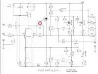
Looking at the Aleph J schematic, the inverting input shows a coupling capacitor, whereas the non-inverting input does not. I have seen this in some other schematics, too. What is the purpose of the capacitor in the inverting input? Why do some amps use is, and others don't?
I wondered about the same thing myself....
How to roll of dc gain to unity via an opamp ac amplifier..? - Electrical Engineering Stack Exchange
Hence, I took the liberty of modifying the balanced-IN, to a single-ended-IN section of the original circuit diagram
If not appropriate (because the original circuit is trademarked), the moderators can delete the post.
Nick
Attachments
Last edited:
Ok, now I understand what the capacitor does. But why is unity gain at DC desired? Why is the capacitor not always there with amps that have a similar input stage?
idiotproof part
that's why are so rare broken PL amps ......... there are plenty of chaps around, not knowing that their sources/preamps are critical - having some steady or temporary DC on output
that's why are so rare broken PL amps ......... there are plenty of chaps around, not knowing that their sources/preamps are critical - having some steady or temporary DC on output
Do you want to amplify any DC that might be present at the input? What about subsonic frequencies..?? Do you enjoy watching the bass membrane moving at few hertz?
The capacitor helps roll-off the gain to unity (no gain) at DC, so that only the desired spectrum (20 - 20kHz) is amplified at a full gain.
The capacitor helps roll-off the gain to unity (no gain) at DC, so that only the desired spectrum (20 - 20kHz) is amplified at a full gain.
Why is the capacitor not always there with amps that have a similar input stage?
If you come across such an amp, post the schematics.
Aleph J is also DC-coupled (but intended for wide masses, even un-initiated ones...) - hence the need for the capacitor C1.
Mighty ZenMod intended his amp for those who have been initiated, those who supposedly do know what they are doing, and trust their pre-amps / sources.
Mighty ZenMod intended his amp for those who have been initiated, those who supposedly do know what they are doing, and trust their pre-amps / sources.
.... however, accidents do happen, so I think it is really wise to keep that C1 as an idiot-proof, safety precautionary measure.
It's important to understand that the C1 is in signal path even if Aleph J is wired for a single-ended input (RCA input); its quality is as important as if it was placed at the input, as a "series" capacitor.
It's important to understand that the C1 is in signal path even if Aleph J is wired for a single-ended input (RCA input); its quality is as important as if it was placed at the input, as a "series" capacitor.
- Home
- Amplifiers
- Pass Labs
- Aleph J for Universal Mounting Spec