It comes with practice. Heat two legs simultaneously with a suitable iron and apply a pulling force at the correct angle, quickly swap to the lead... and its out, as quick as that.
Solder braid is goo at removing excess solder but if the holes are plated through then you still need to heat and wiggle
Solder braid is goo at removing excess solder but if the holes are plated through then you still need to heat and wiggle
It's implied, but not specifically stated...
1) Nice wide tip with an iron that can "hold the heat". Don't want to sit there holding the iron on the legs for an hour. Durable devices, sure, but it'll also save some frustration. In and out. I desolder at higher temps than I solder. Just me. Don't know if that's recommended, but it works for me.
2) Add some flux if you have it. If not... believe it or not... add some fresh solder to help reflow / melt the existing solder much more quickly.
3) Don't worry about removing all the solder at first. Focus on removing the part quickly and easily. Then you can clean up the pads / holes to your satisfaction to allow putting in either the new part or the existing part more easily. I had tried to get each hole crisply clean and let the part just fall out in the past. Sure... it can be done... but it's way easier for me to let the iron do the work and just wiggle and jiggle as previously suggested.
I'm sure there are people with far more expertise, but once I focused on those 3 things, desoldering 3-legged critters became much, much easier for me.
Good luck!
AMPCAMP 1 Yard Line
Let me start by saying that I am an electronics DIY neophyte so please be patient. Also, I haven't used an online forum in some time so if I dorked the post up, thanks to the mods for moving it to the right place.
I just finished my build and am happily listening to my new amp. My issue is that if I fully connect the RCA to Input A, only that channel plays. If I pull the cable out just a bit, both sides light up and everything is fine. I could leave it this way but I'm a bit obsessive so...
Here is what I have done:
1. I have been searching this forum but have not stumbled upon a like thread.
2. I tested other cables and ensured that the source was not suspect.
3. This only happens with Input A. Input B works as expected.
4. The RCA jack appears not to be touching the enclosure. I would have to desolder in order to remove/reinsert so want to be sure that is a valid troubleshooting step before doing so.
5. I followed the 1.8 wiring and build guides.
6. Ensured that the solder points were secure.
I'm sure that this is a no brainer for the more initiated so figured I would give it a shot.
I can't just think what you might have done but it sounds like there is a basic error in the input wiring somewhere.
Begin by doing a basic check (amp OFF) of the resistance between inner and outer of both RCA sockets and see what happens when you fully insert the plug. Does any then show a short.
Don't assume the good channel is the one that is OK... again can't just think of what you have done but it could be this channels wiring at fault.
Try and locate the problem by resistive continuity checks with the amp off and look for any short that appears when the plug is in and how that might occur.
Maybe you have mixed a ground a signal wire somewhere. Its something I would need in front of me to visualise what might have happened.
(also remember the speaker terminals are connected differently to how you might expect, the positive terminal goes to ground and the negative terminal is the 'live' signal output to account for the phase inversion of the ACA)
... If I pull the cable out just a bit, both sides light up and everything is fine...
Do you mean that one LED is off and lights up when you pull the RCA out a little? Or just that you get sound from both sides.
Does changing the switch position from central to up or down make any difference?
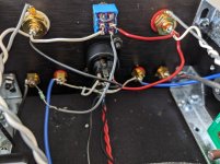
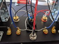
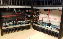
Can you post some clear pictures of the build especially the rear panel and wiring to each board please?
Ah, good point. I should have used a different adjective to indicate that both sides are playing...
Both LEDs are lit at all times. I chose to link to the images due to their size so hope this works like I think it does.
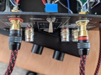
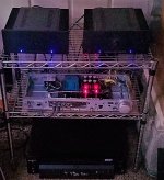
Back plate from above
Back plate from below
Back plate left side
Back plate right side
RCAs plugged in and working (note the right plug depth)
Both LEDs are lit at all times. I chose to link to the images due to their size so hope this works like I think it does.
Back plate from above
Back plate from below
Back plate left side
Back plate right side
RCAs plugged in and working (note the right plug depth)
Attachments
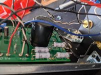
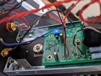
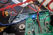
You have the input white wire going to ground terminal on the Back plate right side picture... Swap it round with the grey (ground) wire at the board. Grey to G and White to +In.
Alan
That did it. Thanks for the assist. I am now the owner of a great little amp. It's running through a Rotel 972 preamp then to a set of AR2ax drivers.
Question on hook up.
I bought 2 ACAs a couple years back and built one then as a V1.6. I recently ordered the new back plate, and switch, and built my second one as a V1.8. The second build has now had a week of burn-in in the stereo mode and its just as dandy as the first build.
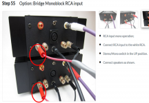
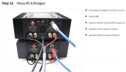
Now, its Friday and I want to take it to the next step and run the two amps in the different modes, starting with Mono RCA Bridged. After reviewing both build guides I have noticed a difference in the pictures. The way the positive and negative speakers terminals are hooked up to the amplifiers appear to be reversed. I don't know if this is intentional or not and if it matters or not but I sure would feel better if someone could inform/educate me about it before I hit that power button.
Should they be hooked up differently?
I bought 2 ACAs a couple years back and built one then as a V1.6. I recently ordered the new back plate, and switch, and built my second one as a V1.8. The second build has now had a week of burn-in in the stereo mode and its just as dandy as the first build.
Now, its Friday and I want to take it to the next step and run the two amps in the different modes, starting with Mono RCA Bridged. After reviewing both build guides I have noticed a difference in the pictures. The way the positive and negative speakers terminals are hooked up to the amplifiers appear to be reversed. I don't know if this is intentional or not and if it matters or not but I sure would feel better if someone could inform/educate me about it before I hit that power button.
Should they be hooked up differently?
Attachments
Well from a “Hitting the power button” standpoint, there will be no issue, it’s not going to hurt anything.
The photos in the 1.8guide are wrong, the speaker red should attach as shown in the 1.6 photo.
That said, try the speakers connected both ways, (inverted or not) I suspect one may sound a little better than the other, and just run with that, as you might have an inverting component upstream, or not…
Thank you for verifying no damage will be done and pointing me to the previous posts.
Makes sense now, I was confused with the writing on the panel its self vs pic too. I will definitely try both ways.
They are happily playing now along with my WHAMMY as a preamp.
Makes sense now, I was confused with the writing on the panel its self vs pic too. I will definitely try both ways.
They are happily playing now along with my WHAMMY as a preamp.
Attachments
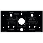
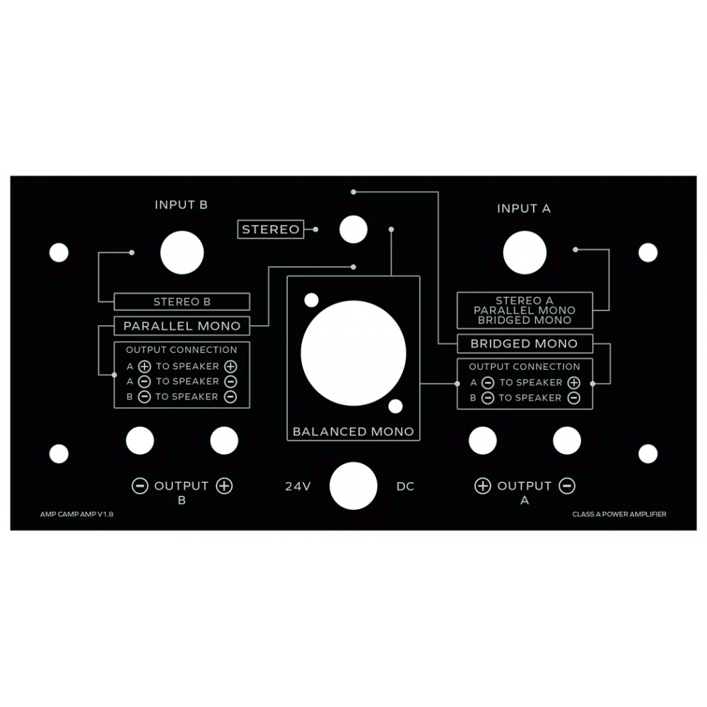
Captain, no, sadly not. The back plate of the V1.8 states for bridged RCA: A- to speaker "-" and B- to speaker "+" - the photo however shows the speaker "+" in A-. The picture for xlr bridged is okay. This is perhaps the reason of the confusion; to the right of the xlr-connector is the description for xlr bridged, and to the right of this description is the one for RCA bridged.
Ah! Plott, it looks like you got to my post before I deleted it!! It seems there have been 2 versions of the printed back plate, both marked as v1.8. I saved a copy from somewhere on the forum earlier in the year to use as a template for the holes on my own case. The wiring guide printed on this differs to the version in the photos recently posted for bridged mono. Not sure if any of these were ever sold?
Attachments
to add to confusion ( or ?) , here is Modushop page, actual one :
Retro per ACA V1.8
image hot-linked:
Retro per ACA V1.8
image hot-linked:
- Home
- Amplifiers
- Pass Labs
- Amp Camp Amp - ACA