I'm with you on that. Unfortunately some posters assume everyone here are EE's.
It's the b+ that threw me.
.
B+ is the psu dc supply voltage, 18v or 24 volts...this being a single rail psu type, b+ can be used...
You're missing the point. Why the term "b+" ? If the B is for battery, why use it for the ACA that doesn't run off a battery?
I even looked on the PCB for B+ and it's not there.
This thread is frequented by noobs (like me) because the ACA is supposed to be an entry-level amp build. Save the cryptic terminology for the more advanced threads, please.
.
I even looked on the PCB for B+ and it's not there.
This thread is frequented by noobs (like me) because the ACA is supposed to be an entry-level amp build. Save the cryptic terminology for the more advanced threads, please.
.
I would love to hear what your opinion is with the 30.2!!! Those are my dream speakers. One can always dream.
Just be sure to turn both AMPs on, as in your pic you have one on and the other off... that is certainly the recipe to very weird stereo imaging problems!
Joking aside, love your front panel finish on the ACAs!
Haha. Of course. Amps aren’t hooked up in that pic so the buttons aren’t completely right.
You're missing the point. Why the term "b+" ? If the B is for battery, why use it for the ACA that doesn't run off a battery?
I even looked on the PCB for B+ and it's not there.
This thread is frequented by noobs (like me) because the ACA is supposed to be an entry-level amp build. Save the cryptic terminology for the more advanced threads, please.
.
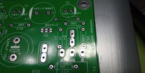
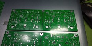
sorry to disappoint you, but in my boards B+ is clearly marked, likewise the ground pads, output pads, i have done around 70+ boards since we started build outs and teach ins with this ACA amp...in 2019....
Attachments
Last edited:
I built two of these in the last couple of months. They are hooked up in mono with XLR. One plays louder than the other by about 6 or 7 db. I checked biasing. That looks fine. Any ideas?
the feedback 68k resistors and the input 10k resistors, check to see that they are the same on both boards...also the 10ufd coupling caps......
also, make sure the output node before the 3300ufd/25v caps are adjusted to 1/2 of b+, so that if your psu is 24vdc, then 12vdc must be set by the only trimpot in the board...
sorry to disappoint you, but in my boards B+ is clearly marked, i have done around 70+ boards since we started build outs and teach ins with this ACA amp...in 2019....
That doesn't look like an ACA board.
I don't see the B+ on the older ACA boards and neither is it on the 1.6 ACA boards.

That doesn't look like an ACA board.
I don't see the B+ on the older ACA boards and neither is it on the 1.6 ACA boards.
that is because we designed our own board layouts...and had it fabricated by JLPCB....
the board i posted was a 2 in 1, two channels in a single board....
Well, no wonder we didn't know what you were talking about.that is because we designed our own board layouts...and had it fabricated by JLPCB....

.
Hi Skylar88
Where are you in your process? I read back a few pages, but this thread moves quickly.
See link below and steps 51-52 for the precise steps to be taken.
Amp Camp Amp V1.6 Build Guide - diyAudio Guides
If that doesn't help, can you point back to the post(s) where you describe your issue, please.
Where are you in your process? I read back a few pages, but this thread moves quickly.
See link below and steps 51-52 for the precise steps to be taken.
Amp Camp Amp V1.6 Build Guide - diyAudio Guides
If that doesn't help, can you point back to the post(s) where you describe your issue, please.
Last edited:
Thanks for your generous offer to help, ItsAllInMyHead. I don't have an issue per se. My ACA is built and working beautifully.
I was just pointing out that I also don't understand the cryptic terminology used in post #9874 and the subsequent question as to what it means.
..
.
I was just pointing out that I also don't understand the cryptic terminology used in post #9874 and the subsequent question as to what it means.
..
.
I built two of these in the last couple of months. They are hooked up in mono with XLR. One plays louder than the other by about 6 or 7 db. I checked biasing. That looks fine. Any ideas?
Are they V1.6 or V1.8 builds?
If you use them as individual Stereo amplifiers via the RCA inputs (not Bridged/XLR) do both channels play at the same volume?
1, Check the resistance from the centre of the RCA connector to the outer ring. It should be about 50KΩ if all is well. If you built from the DIY kit and or BOM, then the feedback resistor (R12) value is 39.2KΩ.
2, Check the resistance between the red and black speaker terminals, it should be 500Ω to 1KΩ.
Compare the 'good' channel against the 'problem' one for clues too.
Alan
Yes bias set with no problem. I am having to wait a week or so for replacement resistors but was wondering if having r12 as 39.2ohms instead of 39.2k as I did would have the effect of almost zero level sound output?It means setting the bias such that at the test point you get half the supply voltage.
I think you have done that, and it worked out correctly.
Yes because the input signal is effectively shorted to ground by the 39Ω resistor.
Think of it as if R11 and R12 are a potentiometer. With the correct values (10K and 39K) The signal is tapped at 3/4 of the input to C3. Now you had 10K and 39 ohm resistor. That is the same as a 10k potentiometer turned right down...
Think of it as if R11 and R12 are a potentiometer. With the correct values (10K and 39K) The signal is tapped at 3/4 of the input to C3. Now you had 10K and 39 ohm resistor. That is the same as a 10k potentiometer turned right down...
Last edited:
So I followed Alan's advice regarding the offending zero ohm rca channel and yes there is a tiny blob of solder seemingly joining the + and - , will clean this up later and for sure it is the reason for the problem.
It's funny but when I read through this thread about a month ago I couldn't believe how many wrong resistors and solder shorts cropped up, how could people make such simple mistakes I thought and now I've gone and done it myself
It's funny but when I read through this thread about a month ago I couldn't believe how many wrong resistors and solder shorts cropped up, how could people make such simple mistakes I thought and now I've gone and done it myself
Harbeth P3ESR vrs 30.2
I have heard both and prefer the small ones, they are less coloured, the big ones have some issues with boxiness.
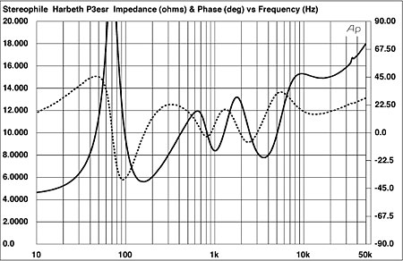
The impedance suggests the P3ESR might be happier with the lower Rout of parallel monobloks.
dave
- Home
- Amplifiers
- Pass Labs
- Amp Camp Amp - ACA