I do a lot with Arduino anyway, and enjoy them. Although if it's not going to do more than control a fan, it's probably over kill. I'll look at the controllers over at Ebay... there's a bunch of them to choose from!
Can you point me to the power supply you use? A quick Google search and searching the Mean Well site didn't turn up anything, but there's so much, I'm probably just overlooking it.
Thanks!
Can you point me to the power supply you use? A quick Google search and searching the Mean Well site didn't turn up anything, but there's so much, I'm probably just overlooking it.
Thanks!
The ACA input buffer will run around 3.5 to 4 mA in order to bias the ouput MOSFET, Q1, to achieve a Vds of 12 Volts. So typical B grade LS170s or the Toshiba BL grade equivalent are what you want. Matching between channels isn't necessary, but won't hurt, obviously. The two MOSFETs Q1 and Q2 don't need to be matched on a board, either. In fact, they don't need to be IRFP240s. I'm getting wonderful sound from one of my amps with IRFP140s and higher rail and bias voltages. Lots of fun to be had experimenting with the little amp.
Pass DIY Addict
Joined 2000
Paid Member
Fidget: what a GREAT looking implementation of the ACA! Nicely done! I like the look of your wooden chassis with the corner feet. Do you have any photo detail of how the feet are constructed and attached? I'm contemplating something similar for a tube build I have in mind.
Thanks Eric!
Yes, I took a few pics while I was building it.
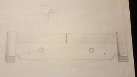
The drawing below was my concept drawing. It probably shows it the most clearly.
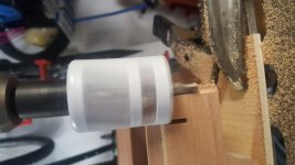
I used a hole saw the same diameter as the dowel to knock the corners off and a strap clamp to hold it together while the glue dried.
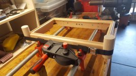
It was originally glued up square with mitered corners because that made the router work easy. Then the inside corners where glued in to provide support when I removed the mitered corner. Then the dowels were glued in place.
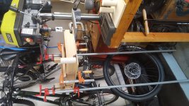
The triangle braces like in the drawing would've worked better than what you see in the pics below. I did it this way because I broke my right hand (and I'm right-handed) at the start of this project. I did almost all of it (and the O2 from the first pics) with my left hand and a bunch of clamps. It took almost 3 weeks!
Sorry the portrait oriented pics get turned sideways... you can still see what's going on, though.
Good luck with yours, I'd love to see your pics!
Do you have any photo detail of how the feet are constructed and attached?
Yes, I took a few pics while I was building it.
The drawing below was my concept drawing. It probably shows it the most clearly.
I used a hole saw the same diameter as the dowel to knock the corners off and a strap clamp to hold it together while the glue dried.
It was originally glued up square with mitered corners because that made the router work easy. Then the inside corners where glued in to provide support when I removed the mitered corner. Then the dowels were glued in place.
The triangle braces like in the drawing would've worked better than what you see in the pics below. I did it this way because I broke my right hand (and I'm right-handed) at the start of this project. I did almost all of it (and the O2 from the first pics) with my left hand and a bunch of clamps. It took almost 3 weeks!
Sorry the portrait oriented pics get turned sideways... you can still see what's going on, though.
Good luck with yours, I'd love to see your pics!
Attachments
Pass DIY Addict
Joined 2000
Paid Member
Wow - great work, and one handed, too! Years ago, I broke my left (dominant) arm and life pretty much sucked learning how to do everything with the "wrong" hand. Thanks for sharing the details. I'm trying to decide whether or not to go with an exotic (and expensive) hardwood for the chassis, or use something more readily available. So many decisions! I still need to purchase some PSU caps and a few chokes for my tube amp then I'll be ready to look at construction details.
Thanks Eric!
Yes, I took a few pics while I was building it.
The drawing below was my concept drawing. It probably shows it the most clearly.
I used a hole saw the same diameter as the dowel to knock the corners off and a strap clamp to hold it together while the glue dried.
It was originally glued up square with mitered corners because that made the router work easy. Then the inside corners where glued in to provide support when I removed the mitered corner. Then the dowels were glued in place.
The triangle braces like in the drawing would've worked better than what you see in the pics below. I did it this way because I broke my right hand (and I'm right-handed) at the start of this project. I did almost all of it (and the O2 from the first pics) with my left hand and a bunch of clamps. It took almost 3 weeks!
Sorry the portrait oriented pics get turned sideways... you can still see what's going on, though.
Good luck with yours, I'd love to see your pics!
Great work! It's so nice to see something outside of the box done so well. (Ignoring the fact that it's still in a box....)
I'm an amateur wood worker as well. Thanks for the inspiration. If imitation is the sincerest form of flattery, I hope anything I might do will turn out so nicely!
I'm trying to decide whether or not to go with an exotic (and expensive) hardwood for the chassis, or use something more readily available.
I used red grandis, which I hadn't heard of before. It was recommended by an employee at Woodcraft.
I found it to be quite easy to work with, very stable, finely grained, and took a water-based finish quite well. And very reasonably priced!
https://www.trada.co.uk/wood-species/red-grandis/
Thanks for the inspiration. If imitation is the sincerest form of flattery, I hope anything I might do will turn out so nicely!
Thank you, Trismos, that's very nice of you to say. If I can be an inspiration, I'm honored.
Hello Everyone,
Apologies if this is answered elsewhere. Could someone please direct me on this ACA issue:
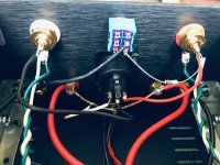
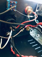
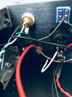
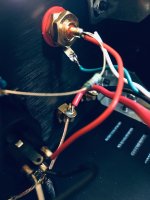
Built ACA 1.6 kit with included front panel switch and back toggle switch wired as shown in batch 3 and step 49 video.
Problem: connecting only one input, either red or white, results in both speakers producing sound, regardless of rear toggle switch setting. Toggle up has slightly higher output. Connecting both L&R (red + white) inputs simply produces higher volume.
So far I have reconfirmed that everything is wired properly and according to wiring diagrams.
Is the problem that it is only working in mono? Could it be the switch or the 39K resistor has gone bad? I would very much appreciate some skilled troubleshooting and resolution advice. - Thanks
Apologies if this is answered elsewhere. Could someone please direct me on this ACA issue:
Built ACA 1.6 kit with included front panel switch and back toggle switch wired as shown in batch 3 and step 49 video.
Problem: connecting only one input, either red or white, results in both speakers producing sound, regardless of rear toggle switch setting. Toggle up has slightly higher output. Connecting both L&R (red + white) inputs simply produces higher volume.
So far I have reconfirmed that everything is wired properly and according to wiring diagrams.
Is the problem that it is only working in mono? Could it be the switch or the 39K resistor has gone bad? I would very much appreciate some skilled troubleshooting and resolution advice. - Thanks
I do a lot with Arduino anyway, and enjoy them. Although if it's not going to do more than control a fan, it's probably over kill. I'll look at the controllers over at Ebay... there's a bunch of them to choose from!
Can you point me to the power supply you use? A quick Google search and searching the Mean Well site didn't turn up anything, but there's so much, I'm probably just overlooking it.
Thanks!
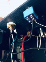
I'm sorry I missed this message. Here is the PSU I'm using:
EPS 120-24.
Datasheet
Connector CN101 is a 12V tap for a fan
I have a couple of tests / ideas you could try, until someone else points into a better direction:
- Have you checked with a multimeter that the back switch is actually changing from continuity to open on the two pins you have soldered the wire and resistor?
- Is there a chance there is continuity between the XLR pins (for instance if you have a jumper shorting the input pins)? Check with a multimeter that there is no continuity between both pins in the XLR.
I would try to isolate the problem by going back step by step until you have something working. E.g. try to see if you can get RCA inputs working as "standalone" for both channels. E.g. start to unsolder resistor from switch to right RCA input and maybe also the red wire from XLR connector. Then check if right channel works as it should using RCA input.
So I finally finished my first ACA (got a pair). I've done one other point-to-point soldering project but never on a circuit board. I got the nice Hakko soldering station and it was a real joy. I took extreme care with everything, triple checking everything and I am sure I took way more time than most but it's working great! Great project and it got me excited to look for another electronics project.
Two questions
1) Bias adjustment with P1 is very sensitive, like very, very. So first off, is that normal and second how precise should I get the voltage reading? I got 1 almost exact 11.9x but the other is around 11.5x vs the stated 12v. Overcoming he pots sticktion pushes me out of range so easily...
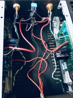
2) With no experience with this sort of thing, I left many of the wires longer than pictured in the guide. Most wires are around +1 inch or so. Is it worth cleaning that up?
Thanks for any advice.
Two questions
1) Bias adjustment with P1 is very sensitive, like very, very. So first off, is that normal and second how precise should I get the voltage reading? I got 1 almost exact 11.9x but the other is around 11.5x vs the stated 12v. Overcoming he pots sticktion pushes me out of range so easily...
2) With no experience with this sort of thing, I left many of the wires longer than pictured in the guide. Most wires are around +1 inch or so. Is it worth cleaning that up?
Thanks for any advice.
- Home
- Amplifiers
- Pass Labs
- Amp Camp Amp - ACA