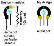
Brian Guralnick said:I want to exactly reproduce the device on the right side of my illustration. The image on the left is missing 1 resistor & it supposed to illustrate how the original schematic works in post #1 of this thread.
Brian,
it is incorrect in your drawing. Essentially inside the attenuator resistors are switched to the ground as well, providing for a "lower" part of the "pot". So in essence for any given attenuation you can replace the lot with just two resistors, same as you can do for a normal pot. My circuit will work OK without the precise load, just in this case the input impedance and precision of steps, especially for small attenuation values, will be affected.
Cheers
x-pro.
The log attenenuator is even older.
 Hi there,
This is my first contribution to this forum. Later on, I intend to post something about myself in the Introductions forum, but first I would like to add a few things to this thread.
A couple of days ago I discovered the diyAudio-site and it took me already most of the evenings since then, hopping from thread to thread. Very interesting. This thread brought me back to the early 90's, I think 1991. Then I designed the same log attenuator as was introduced here. I used the (maybe not so audiophile) 74HC4053 analog CMOS switches (triple SPDT), or maybe it was still HEF4053. My goal was not to design a hi-end audio potentiometer, but simply a volume control for a Public Address amplifier to be controlled by a uC. And I was thinking about making an efficient audio codec based on logarithmic bit spacing, imagine a dynamic range of >120dB with only 8 bit-coding, the noise floor is dynamically modulated and masked by the audio signal itself. This project never started.
But I did not invent the attenuator myself: I was triggered by the design of a thick film hybrid that was available in these days. It took me some time today to find it back, but I still did have some samples in a drawer. It was the CDG4469 from Topaz Semiconductor. This hybrid contains a single channel 256 position attenuator. Each step is 0.5dB, so it has a 127.5dB range. If I remember correctly it uses DMOS switches and calibrated thick film resistors. I used to have a databook of Topaz, but some 5 years ago I dumped some shelves of databooks, since everything is on Internet now. Why waste space? Regret, regret. Topaz does not exist anymore, and nothing can be found back on the web about their products. So, if someone has a datasheet left, I would appreciate. Anyway, the production date on the hybrid is 8652, i.e. week 52 of the year 1986. This means the whole idea of the log attenuator is already quite old.
A bit more searching in some old piles of paper even revealed how I calculated the resistors in the chain. The datasheet of the CDG4469 only showed a basic diagram how the thing was build, but (of course) no resistor values were given. I had to derive the formulas myself. I will not show the complete calculation, but at the end of the page it shows:
If K=gain of one section, expressed as a value between 0 and 1, and Z is the typical impedance of the circuit, then the series resistor to the next section R1= (Z/K)-Z and the shunt resistor to the ground of that section, R2=(Z*K/(1-K))+Z.
Example: Z=1000 (1kOhm) and K=0.5 (-6dB), then R1=1000 and R2=2000. The source impedance that starts the ladder is 1000 and the load impedance should be 1000.
Take note, that even with all pass switches closed and all shunt switches open, the gain is still -6dB, i.e. 6dB attenuation, just because of the load impedance loading the source impedance. This kind of circuits does not have 0dB pass gain. One -6dB section in combination with proper source and load impedance gives -12dB if activated and -6dB if not activated.
One last remark about the CDG4469: it used the L-type attenuator sections for all but the most significant bit, the 64dB section used a T- or PI- attenuator, probably because otherwise the ratio between R1 and R2 would become too big for a thick film circuit. The characteristic Z of the CDG4469 was 650 Ohms.
Steven
Hi there, This is my first contribution to this forum. Later on, I intend to post something about myself in the Introductions forum, but first I would like to add a few things to this thread.
A couple of days ago I discovered the diyAudio-site and it took me already most of the evenings since then, hopping from thread to thread. Very interesting. This thread brought me back to the early 90's, I think 1991. Then I designed the same log attenuator as was introduced here. I used the (maybe not so audiophile) 74HC4053 analog CMOS switches (triple SPDT), or maybe it was still HEF4053. My goal was not to design a hi-end audio potentiometer, but simply a volume control for a Public Address amplifier to be controlled by a uC. And I was thinking about making an efficient audio codec based on logarithmic bit spacing, imagine a dynamic range of >120dB with only 8 bit-coding, the noise floor is dynamically modulated and masked by the audio signal itself. This project never started.
But I did not invent the attenuator myself: I was triggered by the design of a thick film hybrid that was available in these days. It took me some time today to find it back, but I still did have some samples in a drawer. It was the CDG4469 from Topaz Semiconductor. This hybrid contains a single channel 256 position attenuator. Each step is 0.5dB, so it has a 127.5dB range. If I remember correctly it uses DMOS switches and calibrated thick film resistors. I used to have a databook of Topaz, but some 5 years ago I dumped some shelves of databooks, since everything is on Internet now. Why waste space? Regret, regret.
Topaz does not exist anymore, and nothing can be found back on the web about their products. So, if someone has a datasheet left, I would appreciate. Anyway, the production date on the hybrid is 8652, i.e. week 52 of the year 1986. This means the whole idea of the log attenuator is already quite old.A bit more searching in some old piles of paper even revealed how I calculated the resistors in the chain. The datasheet of the CDG4469 only showed a basic diagram how the thing was build, but (of course) no resistor values were given. I had to derive the formulas myself. I will not show the complete calculation, but at the end of the page it shows:
If K=gain of one section, expressed as a value between 0 and 1, and Z is the typical impedance of the circuit, then the series resistor to the next section R1= (Z/K)-Z and the shunt resistor to the ground of that section, R2=(Z*K/(1-K))+Z.
Example: Z=1000 (1kOhm) and K=0.5 (-6dB), then R1=1000 and R2=2000. The source impedance that starts the ladder is 1000 and the load impedance should be 1000.
Take note, that even with all pass switches closed and all shunt switches open, the gain is still -6dB, i.e. 6dB attenuation, just because of the load impedance loading the source impedance. This kind of circuits does not have 0dB pass gain. One -6dB section in combination with proper source and load impedance gives -12dB if activated and -6dB if not activated.
One last remark about the CDG4469: it used the L-type attenuator sections for all but the most significant bit, the 64dB section used a T- or PI- attenuator, probably because otherwise the ratio between R1 and R2 would become too big for a thick film circuit. The characteristic Z of the CDG4469 was 650 Ohms.
Steven
Hi Steven,
thanks for the information. I was somewhat suspicious that this circuit is (as usually the case with something that simple), a forgotten old idea") . On the other hand I am quite happy that in this case there is no possible problems in using it now. Just as well I'm no longer working for Creek .
. On the other hand I am quite happy that in this case there is no possible problems in using it now. Just as well I'm no longer working for Creek .
Cheers
Alex
thanks for the information. I was somewhat suspicious that this circuit is (as usually the case with something that simple), a forgotten old idea
. On the other hand I am quite happy that in this case there is no possible problems in using it now. Just as well I'm no longer working for Creek . Cheers
Alex


x-pro said:
Brian,
it is incorrect in your drawing. Essentially inside the attenuator resistors are switched to the ground as well, providing for a "lower" part of the "pot". So in essence for any given attenuation you can replace the lot with just two resistors, same as you can do for a normal pot. My circuit will work OK without the precise load, just in this case the input impedance and precision of steps, especially for small attenuation values, will be affected.
Cheers
x-pro.
Well, I sat & thought, thought some more. In actually, both yours and my circuit would end up doing the same, except, mine is 2x the stuff. It would be like putting 2 log pots back-back, the only gain would be the perfect mute & maybe, some difference in load effect in the above 10Mhz range. I guess I would be better off adding 1 last relay for the full mute.
Thanks for beign patient & answering my questions. I've managed my battery powered attenuator PCB layout to conform to 4 different POT methods, including this 1. It's done just by changing the value, location, & orientation of the SMD resistors. If you want a few blank PCBs, email me privately.
Now, to play with the equasions in promethius' earlier post.
For those who are unfamiliar with stepped attenuators & how many steps, or bits they might need, I made a digital simulation, go here:
http://www.diyaudio.com/forums/showthread.php?postid=247296#post247296
For most, even 4, or 5 bits should be fine.
Just found some documentation on my old digital pre which used the same type of attenuator as volume control.
For those who want to know how to calculate the resistor values of the circuit in the first post, I've attached an excerpt where I derive the formulas. Although it's in German, I think it is easy to understand from the picture and the equations.
For those who want to know how to calculate the resistor values of the circuit in the first post, I've attached an excerpt where I derive the formulas. Although it's in German, I think it is easy to understand from the picture and the equations.
Attachments
AMT-freak said:Just found some documentation on my old digital pre which used the same type of attenuator as volume control.
For those who want to know how to calculate the resistor values of the circuit in the first post, I've attached an excerpt where I derive the formulas. Although it's in German, I think it is easy to understand from the picture and the equations.
How about an english version?
promitheus said:If you don´t understand the german Text you can just use my equations in the previous postings.
Already read yours. I just enjoy gathering many different means of describing the exact same formula.
Thank you, both, AMT-freak & promitheus.
Triming resistors, a milliohm meter.
Since it would cost less to trim our own resistors for this log pot, NE1 Know of the cheapest ohm meter which would allow me to trim a 5.xxxx Ohm resistor to better than 0.05%?
Perhaps, a milliohm meter, except then I stilll need a .05% meter for the above 100.00 KOhm range resistors.
Since it would cost less to trim our own resistors for this log pot, NE1 Know of the cheapest ohm meter which would allow me to trim a 5.xxxx Ohm resistor to better than 0.05%?
Perhaps, a milliohm meter, except then I stilll need a .05% meter for the above 100.00 KOhm range resistors.
Hi Brian,
There is no need to use such accurate resistors. Normal 1% resistors will do. Suppose an MSB of 32dB, then 1% resistors make an error of approx 0.2dB maximum, which is probably less than your LSB, that will be 1dB or maybe 0.5dB. So 1% resistors keep the volume control still nicely monotonic.
Steven
You missed the 2 points, If I can trim resistors, why not do it right the first time.
OK, .5% is good enough for me, but, my current crummy meter reads 5.0 Ohm on a 5 ohm resistor, also, it's trim drifts. I need a meter which is at least 10x better for single digit ohms, without drifting due to local humidity, local temperature & it's lousy calibration pot. If I'm going to buy a new meter, make it a good 1.
OK, .5% is good enough for me, but, my current crummy meter reads 5.0 Ohm on a 5 ohm resistor, also, it's trim drifts. I need a meter which is at least 10x better for single digit ohms, without drifting due to local humidity, local temperature & it's lousy calibration pot. If I'm going to buy a new meter, make it a good 1.
Microntroller for this attenuator
Is it possible to use the same microntroller code as Till developed at http://home.arcor.de/dddddd-/relais/relais.html ?
Both are 8 bits and switch in a binary mode.
Remember that Till is selling the programmed microcontrollers.
Is it possible to use the same microntroller code as Till developed at http://home.arcor.de/dddddd-/relais/relais.html ?
Both are 8 bits and switch in a binary mode.
Remember that Till is selling the programmed microcontrollers.
Re: Microntroller for this attenuator
Who's design?
Mine uses the PIC16F72, it has a few more IOs.
ErikdeBest said:Is it possible to use the same microntroller code as Till developed at http://home.arcor.de/dddddd-/relais/relais.html ?
Both are 8 bits and switch in a binary mode.
Remember that Till is selling the programmed microcontrollers.
Who's design?
Mine uses the PIC16F72, it has a few more IOs.
Brian Guralnick said:I need a meter which is at least 10x better for single digit ohms, without drifting due to local humidity, local temperature & it's lousy calibration pot. If I'm going to buy a new meter, make it a good 1.
My father surprised me once by dragging an old resistor bridge out of the desktop drawer. I believe the instrument is more than 30 years old....and its spot on with better presicion than ive been able to obtain from any other meter. Unfortunately a resistor bridge seems to be hard to find for reasonable money these days, but if you should stumble on such at a flea market.....dont hessitate to buy it
Cheers
Magura
Oops, I wish I'd seen AMT-freak's post earlier... I derived all the formulas by hand for this... Oh well. Just a word of caution: I believe the formulas on Steven's diagrams are incorrect. Please double-check before you use them.
Here is my version of the spreadsheet. It includes some diagrams from this thread, along with some useful notes. The worksheet also calculates some min and max values based on resistor tolerances used. Enjoy!
Oh well. Just a word of caution: I believe the formulas on Steven's diagrams are incorrect. Please double-check before you use them.Here is my version of the spreadsheet. It includes some diagrams from this thread, along with some useful notes. The worksheet also calculates some min and max values based on resistor tolerances used. Enjoy!
Attachments
- Status
- This old topic is closed. If you want to reopen this topic, contact a moderator using the "Report Post" button.
- Home
- Amplifiers
- Pass Labs
- Constant impedance relay-resistor logarithmic attenuator