Luminaria MR design
No kidding?iron pumpkinz. What sort of spookiness u mean this preamp.
it gives you everything ( attenuation , gain if needed) while not being there
Is it possible to decrease the value of the 10uF Caps without disadvantages?
What is the minimal value?
Thanks
Daniel
if you think of output cap of FE - size is determining lowest frequency while still being linear in phase and level
size depends of Rin of next stage
calc: F=1/(2 x Pi x R x C) [Hz, Ohm, Farad] , in this case R is Rin of next stage
shoot for 2-3Hz , to preserve phase low down
I will use the complementary bias and output stage stage as an amp.
Burning Amplifier Complementary Bias and Output Set for the BA-2 & BA- – diyAudio Store
I see round about 20kOhms. Is this correct?
Burning Amplifier Complementary Bias and Output Set for the BA-2 & BA- – diyAudio Store
I see round about 20kOhms. Is this correct?
I am confused
is this schematic you're looking at ?
Attachments
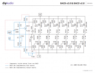
point D (Drive) is - through C101 - in AC realm connected to:
A. gates of all Mosfets,
B. R127,P101+R128
C. R126,R125+P102
ignore A - practically too high impedance
ignore B - everything blocked/bootstrapped with C101
C ........... we are used that usually we see some resistance to GND , looking at it as first suspect fro determining Rin of stage
however , as GND is in most cases just state of mind , or Constructor decision ........ we can observe our usual "GND" as some firm and fixed potential , to which are our critical resistances/impedances connected , loading some arbitrary point being very Jumpy in nature
so - positive rail is GND* for R126 .......... *some call it "virtual GND"
so - negative rail is GND** for R125+P102 ........**some call it "virtual GND"
so , looking from point D , we see two resistors connected with other end to some GND , and we can't see which type of GND are these , so they're practically the same
thus , looking from point D , these two resistors are connected in parallel
thus , Rin is R126 in parallel with R125(+ something small) , so practically Rin=R126//R125 = 15K//15K = 7K5
easy , isn't it ?

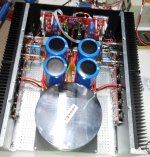
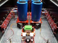
Hello, A new Ba3-Balanced - Ba3 4 channel non complementary is born and signs stable ")
The FE is powered by Salas's shunt stabilizer,
Has some protection to DC, temperature and overloading witb boards under transformer,
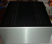
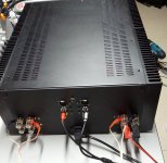
I still have to connect all lights , add bottom shielding ; add temperature shield for capacitors and cnc the front pannel for status indication and thermometer but ... i was so eager to hear it sing as a gratification of the work it took!
No photo gear in my mancave hence lousy photos attached.
The FE is powered by Salas's shunt stabilizer,
Has some protection to DC, temperature and overloading witb boards under transformer,
I still have to connect all lights , add bottom shielding ; add temperature shield for capacitors and cnc the front pannel for status indication and thermometer but ... i was so eager to hear it sing as a gratification of the work it took!
No photo gear in my mancave hence lousy photos attached.
Attachments
Last edited:
I currently have a BA3FE and have been really considering changing it to balanced since I have matching F4s with XLR. Is this just as simple as adding one more matched board, connect R5 on both, and add XLR? Or will I need another transformer and regulated power supply?
Also, does anyone have pics they can share of their finished BA3B preamps so I can see what I am working with?
Also, does anyone have pics they can share of their finished BA3B preamps so I can see what I am working with?
I currently have a BA3FE and have been really considering changing it to balanced since I have matching F4s with XLR. Is this just as simple as adding one more matched board, connect R5 on both, and add XLR? Or will I need another transformer and regulated power supply?
Also, does anyone have pics they can share of their finished BA3B preamps so I can see what I am working with?
I have not done it yet but I was going to use Tom Christiansens universal buffer to provide both balanced and unbalanced outputs in my existing BA3 pre.
Would anyone be willing to walk me through the calcs for determining whether or not the source resistors can be reduced from 1R0 to 0R47 or 0R22 as an example. I read both of Papa's articles related to matching (links below). I understand the concept of attempting to even out the current draw of devices with varying Vgs, and I understood the example for the input devices in "The Art of Matching".
Where I fell off was the example for the output devices and why all the devices have an equal source resistance of 1R0 vs. adding the resistance to the device(s) with the lower Vgs.
The tl;dr is I'd like to use 0R47 or 0R22, and I've heard that is practical. However, I don't know how tightly the devices will need to be matched in order to use either value. I'm comfortable leaving the 1R0, and allowing a bit of "padding" b/c I'm sure my matching won't be perfect. I think the choice also depends on the current, so assume the max bias per device will be 0A7.
I'd love to learn how this is determined.
Thanks!
http://www.firstwatt.com/pdf/art_mos_test.pdf
http://www.firstwatt.com/pdf/art_matching.pdf
- Home
- Amplifiers
- Pass Labs
- Burning Amp BA-3b (Balanced)