Just curious, why not use the existing F1 circuit board layout as a basis? The artwork has been published on page 8 of the F1 service manual:
http://www.firstwatt.com/pdf/prod_f1_srv.pdf
It's a known good design, and the F1J uses the very same layout.
For my part, sometime we can't find exactly the same component as the original pcb then i prefer doing my own pcb. In the same time for the cost i do several amps pcbs and power supply pcbs, for example the the F1J slot i have 7 other amp in a same panel...
Hi Spades,
Making the F1 a more accessible project for other diyAudio members is one of my primary motivations in making these boards. I need to get the first build on them complete and verify that they work well, and then I will post the small number of extra boards in my order in the swap meet. I have started a list of people who are interested and you are at the top") . I will let you know before they go up on the swap meet.
. I will let you know before they go up on the swap meet.
Making the F1 a more accessible project for other diyAudio members is one of my primary motivations in making these boards. I need to get the first build on them complete and verify that they work well, and then I will post the small number of extra boards in my order in the swap meet. I have started a list of people who are interested and you are at the top
. I will let you know before they go up on the swap meet.you need to fatten all energy traces
you can use IRFP in place of Semisouths and it will still sound great
This is a 140µ PCB thikness then no problem with the current...
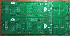
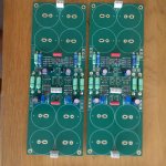
Here are pcbs amps without power supply of F1J, Circltron, Aleph XMM and a main preamp board (with lcd pcb, ir etc) with little pcb which can give me the choice of any preamp.
Attachments
jazzyj - looks like you are making good progress putting your projects together, thanks for posting the pictures!
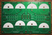
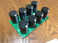
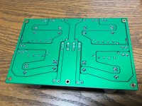
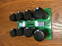
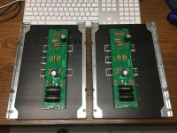
I am making some progress too. The power supply PCB is together and all fit and went well, although at times I felt my 70W soldering iron was less powerful than desired when soldering to the large copper regions (even with thermal reliefs on both sides).
I am making some progress too. The power supply PCB is together and all fit and went well, although at times I felt my 70W soldering iron was less powerful than desired when soldering to the large copper regions (even with thermal reliefs on both sides).
Attachments
Hello yes i have several project in a same time, Hiraga 30w, hiraga le monstre, amps kaneda (50W,192HP) and a DAC preamp active filter.
As you see all my amp have approx the same structure for the cost.
For your circuit the clearance and the relief with is quite dificult to choose.
Next circuit you should reduce the relief width and keep with the same clearance it may be work better.
JMP
As you see all my amp have approx the same structure for the cost.
For your circuit the clearance and the relief with is quite dificult to choose.
Next circuit you should reduce the relief width and keep with the same clearance it may be work better.
JMP
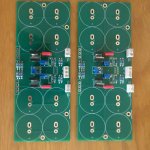
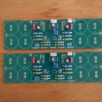
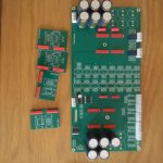
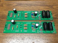
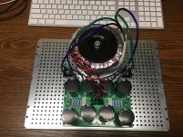
Just sharing some progress photos. The missing parts are either coming on a Mouser order next week, or if they are labeled with number that is over 100 they are optional parts not included in the original schematic of the amp. R1xx resistors are trim resistors that can be added to correct DC offset if needed (as mentioned in Papa's various write ups on the amp), and C101, C102 are for adding 10uF electrolytics for an F1J build.
Attachments
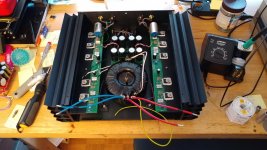

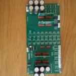
Just a couple progress photos for people patiently waiting for the boards. I am a bit slow, but I have not hit any snags yet. I am hoping for first power on the amp this coming weekend. Note: The leads from the transformer haven't been trimmed to length yet to allow favorable positioning of the transformer to reduce noise after power up.
Attachments
- Home
- Amplifiers
- Pass Labs
- Firstwatt F1J