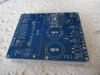
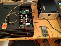
PCB's arrived yesterday from PCBWAY, looks to be very good quality especially considering the price I paid for 70u copper and the short turn around time.
🙂
With some luck they'll be playing music this weekend.
🙂
With some luck they'll be playing music this weekend.
Attachments
Last edited:
How did it go, Tazzz?
I want a pair of f1j pcbs, but I'm not sure how I'd go about getting some. Could you possibly help me out? I'll send you a pm about it, if you don't mind?. I have a matched quad of jfets just lying around, waiting to be put to use.
It's almost embarrassing, I first started thinking about building it a *long* time ago, ordered matched transistors and some parts... and it's just been sitting there in a box.
(I'm curious about how a diy f1j would match up to the j2 that I've been enjoying the last 9 months or so.)
Good evening gentlemen,
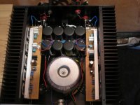
had some spare Semisouth JFETs around from a high efficiency inverter project and so I have finished last week my F1J-clone. I liked the idea and the similarity to the tube amp DPA-300 from Vacuum State:
Power differential amplifier with CCS, no NFB. Okay, maybe not completely comparable, as the tube circuit has effectively two stages and the power devices have triode - character whereas the JFETs are more pentode-like.
Equally I did a J2-clone some weeks ago. As my speakers (JLTI Elsinore Mark5) are designed to work with both, voltage and current output amps I am now in the position to do some comparative listening against two different tube amps (300B and CFB-amp)
F1J has an output impedance of approx. 60 Ohms whereas J2 is listed with 0.4Ohms. So if your speaker does not suit both concepts you may experience some surprise.....
Anyway this is DIY and I`d like to thank Mr. Pass for his generousity in sharing his knowledge.
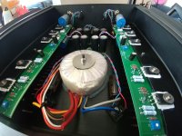
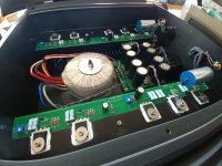
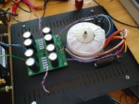
The attached pictures are showing the F1J-Clone. I am not good at working with metal, so I have bought a nice housing form the bay and supplied the guts...
Cheers, Jürgen
had some spare Semisouth JFETs around from a high efficiency inverter project and so I have finished last week my F1J-clone. I liked the idea and the similarity to the tube amp DPA-300 from Vacuum State:
Power differential amplifier with CCS, no NFB. Okay, maybe not completely comparable, as the tube circuit has effectively two stages and the power devices have triode - character whereas the JFETs are more pentode-like.
Equally I did a J2-clone some weeks ago. As my speakers (JLTI Elsinore Mark5) are designed to work with both, voltage and current output amps I am now in the position to do some comparative listening against two different tube amps (300B and CFB-amp)
F1J has an output impedance of approx. 60 Ohms whereas J2 is listed with 0.4Ohms. So if your speaker does not suit both concepts you may experience some surprise.....
Anyway this is DIY and I`d like to thank Mr. Pass for his generousity in sharing his knowledge.
The attached pictures are showing the F1J-Clone. I am not good at working with metal, so I have bought a nice housing form the bay and supplied the guts...
Cheers, Jürgen
Attachments
@pozo
you have what i've been dreaming 😀 Elsinore mk6 with F2J, they will be my next year(s) list
waiting for your impression
you have what i've been dreaming 😀 Elsinore mk6 with F2J, they will be my next year(s) list
waiting for your impression
Finally!
... I realise, when using this amp I have unintentionally removed any feedback from my system. ...with the exception of a DC servo in the preamp.
... I realise, when using this amp I have unintentionally removed any feedback from my system. ...with the exception of a DC servo in the preamp.
Attachments
Last edited:
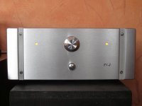
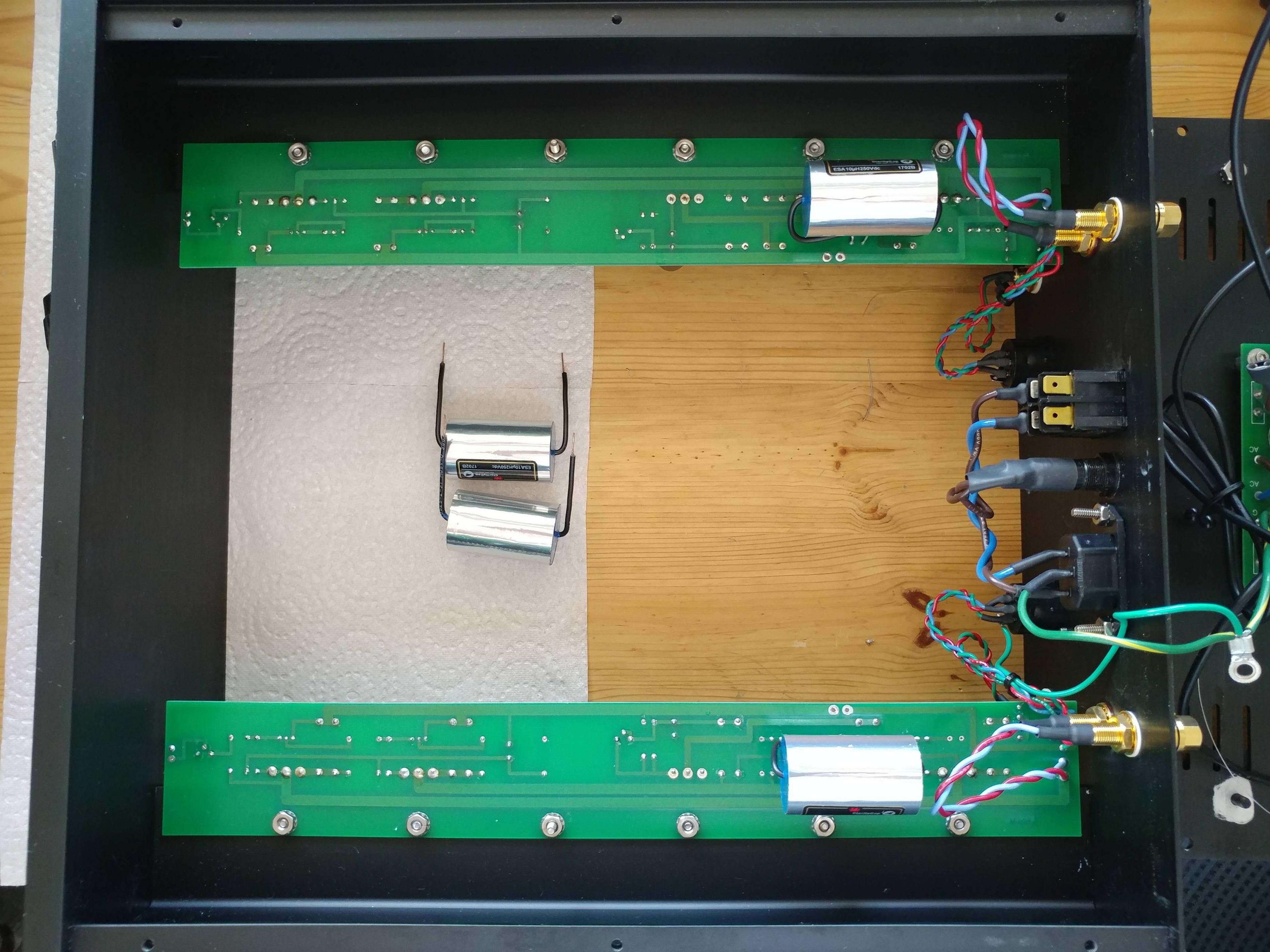
Not too long ago I had the opportunity to acquire an original, Nelson Pass kitchen-table-spec First Watt F1J (S/N 887). And so I did!
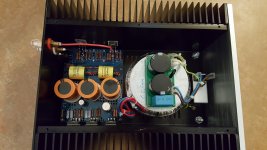
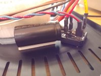
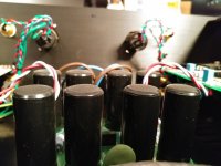
The amp was well looked after, but upon popping the hood I noticed that the PSU caps's tops were a bit bulging (poking the bulges suggested substantial pressure buildup inside). Check it out:

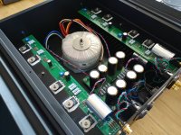
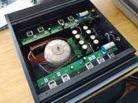
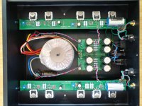
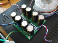
I decided to give the amp a little overhaul, starting with replacing all the PSU caps with new ones, specifically Nichicon UKW 22000uF 25V types.

As you may have noticed, I have also added caps directly at the bridges, simply because it helps me sleep better at night. See the attached PSU pics for details.
I then proceeded to replace the other electrolytic caps with new ones (Panasonic FM for the 1000uF and FR for the 220uF). Furthermore, I replaced the polar Silmic II 10uF caps at the inputs with ClarityCaps ESA 10uF 250V caps. I even measured which lead goes to the outside foil, just to be thorough (also, better sleep).
Apparently you can find the same type of caps in the Pass Labs XP-30 preamp (see http://www.hifishock.org/galleries/electronics/pass-labs/preamplifier/xp-30-2-pass-labs.jpg), so I guess that modification shouldn't be full-on heretic.
After putting it all together again, I'm happy to report that the amp still works fine, measures within specs and sounds lovely with the AKG K1000 headphones.

Be sure to check out the other attached pics, especially the fisheye shots!
Oh, and one last thing: The First Watt amps are massive. For some reason they have always seemed smaller in the online reviews, but irl these amps are really beefy.
The amp was well looked after, but upon popping the hood I noticed that the PSU caps's tops were a bit bulging (poking the bulges suggested substantial pressure buildup inside). Check it out:
I decided to give the amp a little overhaul, starting with replacing all the PSU caps with new ones, specifically Nichicon UKW 22000uF 25V types.
As you may have noticed, I have also added caps directly at the bridges, simply because it helps me sleep better at night. See the attached PSU pics for details.
I then proceeded to replace the other electrolytic caps with new ones (Panasonic FM for the 1000uF and FR for the 220uF). Furthermore, I replaced the polar Silmic II 10uF caps at the inputs with ClarityCaps ESA 10uF 250V caps. I even measured which lead goes to the outside foil, just to be thorough (also, better sleep).
Apparently you can find the same type of caps in the Pass Labs XP-30 preamp (see http://www.hifishock.org/galleries/electronics/pass-labs/preamplifier/xp-30-2-pass-labs.jpg), so I guess that modification shouldn't be full-on heretic.
After putting it all together again, I'm happy to report that the amp still works fine, measures within specs and sounds lovely with the AKG K1000 headphones.
Be sure to check out the other attached pics, especially the fisheye shots!
Oh, and one last thing: The First Watt amps are massive. For some reason they have always seemed smaller in the online reviews, but irl these amps are really beefy.
Attachments
-
 F1J_1.jpg843.6 KB · Views: 1,115
 -
 F1J_2.jpg843.6 KB · Views: 196
 -
 F1J_fish1.jpg748.8 KB · Views: 220
 -
 F1J_fish2.jpg719.2 KB · Views: 207
 -
 F1J_6.jpg828.4 KB · Views: 221
 -
 F1J_5.jpg787.3 KB · Views: 1,094
 -
 psu detail.jpg713.3 KB · Views: 193
 -
 psu1.jpg803.1 KB · Views: 1,049
 -
 psu3.jpg582.4 KB · Views: 150
 -
 bloat.jpg266.6 KB · Views: 1,071
Since my last post I have adjusted P1 according to the F1J upgrade instructions from FIRST WATT F1J and pulled some numbers from the circuit:
V_mains=230.2V AC
Left channel:
V_supply=21.02V DC
V_drain_+=13.80V DC
V_drain_-=13.79V DC
V_diff=5mV DC
Right channel:
V_supply=21.15V
V_drain_+=13.80V DC
V_drain_-=13.86V DC
V_diff=50mV DC
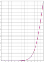
Noise is as low as you'd expect and distortion (single ended source, balanced measurement) goes as low as 0.01%, just as specified.
Everything seems fine, but there is one issue: audible hum from the transformer. What's up with that?
The amplifier is currently on headphone duty, so the amp is at arm's length from my listening spot, which makes the hum very noticeable. The offending transformer is the stock Plitron 2*115VAC/2*18VAC 300VA model that is found in all the First Watt amps.
The only solution I can think of right now is replacing the transformer, I'm thinking toroidy 400VA audio grade (interwinding screen, Gauss band).
Any opinions?
Edit: The sound is glorious btw, this one's a keeper.
V_mains=230.2V AC
Left channel:
V_supply=21.02V DC
V_drain_+=13.80V DC
V_drain_-=13.79V DC
V_diff=5mV DC
Right channel:
V_supply=21.15V
V_drain_+=13.80V DC
V_drain_-=13.86V DC
V_diff=50mV DC
Noise is as low as you'd expect and distortion (single ended source, balanced measurement) goes as low as 0.01%, just as specified.
Everything seems fine, but there is one issue: audible hum from the transformer. What's up with that?
The amplifier is currently on headphone duty, so the amp is at arm's length from my listening spot, which makes the hum very noticeable. The offending transformer is the stock Plitron 2*115VAC/2*18VAC 300VA model that is found in all the First Watt amps.
The only solution I can think of right now is replacing the transformer, I'm thinking toroidy 400VA audio grade (interwinding screen, Gauss band).
Any opinions?
Edit: The sound is glorious btw, this one's a keeper.
Attachments
Last edited:
I would try a larger transformer. Stock F1 circuit draws a lot of current,
and is hard on supplies.
and is hard on supplies.
besides amp being enormously Fugly! , I can observe that you are certainly sleeping well in enormous doses

DC on mains could also cause hum in a toroidal
I would be interested in seeing the distortion spectrum if you saved the measurements ?
The toroidys in my amps are silent though I think they are 400VA per channel
I would be interested in seeing the distortion spectrum if you saved the measurements ?
The toroidys in my amps are silent though I think they are 400VA per channel
Last edited:
Thanks for your input, guys, guess I'll go with the bigger transformer then.
There's not a lot of space towards the PSU pcb for a bigger donut, but I already contacted Tomasz from toroidy and he can provide a transformer with an undrilled center (the epoxy potting thing in the donut hole), allowing me to drill the mounting hole off center to move new the transformer further towards the front of the chassis.
It occurred to me that the amp's current draw can be measured via the voltage over the paralleled resistors in the PSU. The four 1R resistors in parallel should form a 0R25 resistance, dropping a measured 0.933V (right channel), equating to a current of a healthy 3.73A. With the supply voltage of 21.15V, the power consumption equates to rounded 80W. 160W stereo. With a factor three, I'll be shopping for a 500VA transformer, maybe even 600VA if it fits.
I haven't looked at any spectra of the mains yet, but I like the idea (I do recall a waveform with flat tops though). What I do know is that my other amps with silly oversized transformers are dead silent.
I'll keep y'all posted!
Attachments
 [/ATTACH]
.jpg")


 Hi guys
I have some trouble with connections to speaker posts and RCA jack. I will be grateful if some one could help me how to connect it properly. I have very litle knowledge about circuits so I cant figure it out how to connect all this.
Thanks for any help.
Last edited:
Are you selling an F1J clone? If so, please send me a pm. Thanks.No uptick in interest for this gem with the recent availability of matched quads?
Does anyone know of a source for the SemiSouth R100s, or is there an alternative part that can be used in the F1J? My friend who got me into this whole DIY Audio business in the first place has the F1 PCBs but never got around to building himself the amp, so I'd like to return the favor and build it for him...
I don't expect the R100s to be cheap, but I'm having a hard time swallowing $183 for a matched pair, which is what I'm seeing on eBay!
I don't expect the R100s to be cheap, but I'm having a hard time swallowing $183 for a matched pair, which is what I'm seeing on eBay!
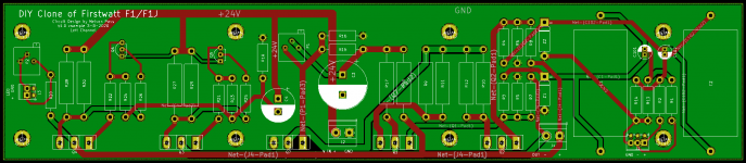
UMS Pattern F1/F1J Board Layout
A friend recently told me about KiCad software, and I thought it would be fun to layout a board for the F1 amp so I could compare it to my F2J clone. A couple hours here and there over the last few weeks resulted the board below. I would love some suggestions/criticism/abuse to help make it better.
I thought the following features would be nice and are on the board:
UMS Mounting Pattern
Plenty of space for 1uF input coupling Film Cap
Location for 10uF Elna Silmic II for F1J input change
Screw terminals for all wiring connections
Thanks!
Attachments
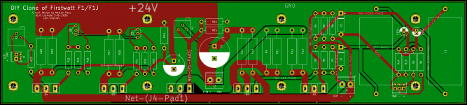
maximize all power traces , route them two-way (top and bottom ) wherever you can
order 70um copper
order 70um copper
maximize all power traces , route them two-way (top and bottom ) wherever you can
order 70um copper
Thanks Zen Mod! Your input is always appreciated.
I have increased the width of the power traces, but there was too much crossing of the top and bottom layers for the two-way routing. Unless I missed something all the high current routing is now as wide or wider than in the original First Watt boards.
Attachments
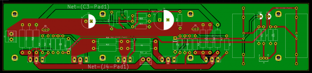
I took a shot at a new layout for the F1 board, primarily focused on getting wider and shorter power traces. This layout has via's on one of the low current traces, are there any reasons to avoid via's? Most of the power traces are also two-way routed. Also, when looking at trace widths, the online calculators ask for an allowable temperature rise. What temperature rise is ok? 1 deg C?
Thanks!
Thanks!
Attachments
- Home
- Amplifiers
- Pass Labs
- Firstwatt F1J