I don't think you'll find an ultimate design or even the concept of supersession. I get the impression that tinkering results in variation after variation, without necessarily having each new design be 'better' than all previous. Instead, I think each new design is merely 'different' in some way or another.I have been reading about the First Watt amps and am particularly intrigued by the idea of the F1(J). Balanced single-ended, class A and current output all sound like good ideas, but importantly the low damping should match very well with the Lowther DX4s and give them a bit more life.
What I can’t work out is if the F1, with the mods for JFET detailed earlier in this thread, is the latest thinking on this design. Has it been superseded by anything? Are any of the Zen series balanced single ended class A transconductance designs?
Basically, are there any other designs I should be looking at?
But to answer your question, if you want to know about other designs then check out my "Concise Guide" - available via link in one of the sticky thread topics under "Pass Labs"
thanks guys,
rsdio your guide is great. I have referred back to it a number of tmes to keep track when I have half a dozen of Nelsons papers open on diferent tabs trying to make sense of it all. I am relying on the little bit of circuit theroy they made us do in a mechanical engineering degree, so this is a fairly steep learning curve for me.
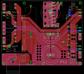
generg, do we really need boards? the circuit looks so simple it could be done on a bread board or point to point. The picture in the manual makes it look like the pcbs were optimised more to fit the heatsinks than for signal paths.
I have plenty of time to plan this one, there's a lot of work still to go on my current project. Soldering may be easier than welding, but I'm slow at both.
I really would like to switch my existing transformers between amps which means adapting either the power supply or the circuits to ±30v. It seems a waste to knock it down to 20v, but I need to do a lot more reading before I'm clever enough to understand how to adapt the circuit without ruining it.
Much will also depend on finding a complimentary I-V linestage circuit to sit between TPAs Buffalo3 DAC and the amp, ideally this would be Jfet, balanced single-ended class A too. Time to re-read the Zen I-V Converter paper...
rsdio your guide is great. I have referred back to it a number of tmes to keep track when I have half a dozen of Nelsons papers open on diferent tabs trying to make sense of it all. I am relying on the little bit of circuit theroy they made us do in a mechanical engineering degree, so this is a fairly steep learning curve for me.
generg, do we really need boards? the circuit looks so simple it could be done on a bread board or point to point. The picture in the manual makes it look like the pcbs were optimised more to fit the heatsinks than for signal paths.
I have plenty of time to plan this one, there's a lot of work still to go on my current project. Soldering may be easier than welding, but I'm slow at both.
I really would like to switch my existing transformers between amps which means adapting either the power supply or the circuits to ±30v. It seems a waste to knock it down to 20v, but I need to do a lot more reading before I'm clever enough to understand how to adapt the circuit without ruining it.
Much will also depend on finding a complimentary I-V linestage circuit to sit between TPAs Buffalo3 DAC and the amp, ideally this would be Jfet, balanced single-ended class A too. Time to re-read the Zen I-V Converter paper...
o.k. I like point to point too, it is a more concentrated work..... and the last F1 boards I had were really not so good, the paths with the high current were very thin.
The building was easy and the sound a real surprise, difficult was for me to get rid of the offset, i had to match the two Semisouth and the other IRF very very precisely and nevertheless I had to correct with some resistors parallel to the source R and so on...
good luck with PTP!
The building was easy and the sound a real surprise, difficult was for me to get rid of the offset, i had to match the two Semisouth and the other IRF very very precisely and nevertheless I had to correct with some resistors parallel to the source R and so on...
good luck with PTP!
No, I don't think you need PCBs. Personally, I prefer to have a PCB made, but I have several fab houses nearby and I do this sort of thing professionally. But you can surely just wire point-to-point, so long as your wires can handle the current and your solder joints are solid.do we really need boards? the circuit looks so simple it could be done on a bread board or point to point. The picture in the manual makes it look like the pcbs were optimised more to fit the heatsinks than for signal paths.
Power supplies are some of the easiest circuits to make, DIY-style. You might be better off saving that ±30 V supply for some other project, and make a ±20 V or +20 V, as needed, specifically for your F1J amp. Granted, the parts to make a good supply are not dirt cheap, but at least it's not very hard to put them together. The savings might outweigh the extra effort, since you'll be wasting fewer Watts if you use a matched supply.I really would like to switch my existing transformers between amps which means adapting either the power supply or the circuits to ±30v. It seems a waste to knock it down to 20v, but I need to do a lot more reading before I'm clever enough to understand how to adapt the circuit without ruining it.
I take your point about matched power supplies. I suppose when you think about class A, the cost of a pair of 0-18v toroids will pay for themselves in power savings over reusing the 24-0-24v ones.
The main reason I want to get this sorted out in my head now is planning the space and heat layout. I am building a pair of quite large open baffle speakers with quickly swapable linestage and amps. I want to mount everything on the backs in steel segregated cases so all the transformers are in one section, the rectifiers/regulators in the next, and the usb&dac, linestages and power amps are in the next. I may not actually build this amp for a year or so, but I want to leave room for it as I build my current project.
The main reason I want to get this sorted out in my head now is planning the space and heat layout. I am building a pair of quite large open baffle speakers with quickly swapable linestage and amps. I want to mount everything on the backs in steel segregated cases so all the transformers are in one section, the rectifiers/regulators in the next, and the usb&dac, linestages and power amps are in the next. I may not actually build this amp for a year or so, but I want to leave room for it as I build my current project.
I use Lowther PM6A and tone tubby and the surrounding Jon suggested on his side as Tiny alnico open baffle....
what did you use?
what did you use?
My plan is DX4s with silver voice coils. I live a few miles away from Lowther and they are the most expensive part of my project so I will wait until everything else is tested before buying them.
For baffles I plan to trim down solid oak doors from the local demolition yard, with sheets of cork set in the recessed panels to absorb reflections. Hinged side panels (more doors cut in half) to make them just under 5ft wide in use and so they can fold away into the corner of the room when not in use. 6ft doors are really cheap because modern houses have taller door frames.
London properties have small rooms so I am hoping that big baffles will give enough bass from the Lowthers alone. I don't want to put too much money into the baffles themselves because I may have to jettison them when we move back to Australia next year.
Longer term this will become my office system and I hope to build a 3- or 4-way system for the bigger rooms in Australian houses, based on the Linkwitz Orions but with crossover and EQ in digital domain.
zkdaz,
I don't know if you can demo them,
I like the Alnico's with no high-ferric, and copper voice coils. I like them better than the DX4's (standard) that I also have. They are tamer.
I don't know if you can demo them,
I like the Alnico's with no high-ferric, and copper voice coils. I like them better than the DX4's (standard) that I also have. They are tamer.
given that they are just down the road in Sidcup, I should be able to arrange a listen before placing the order. i'll give them a call next month once i'm a bit further through soldering and testing.
a lot of people seem to prefer the alnicos, the only comparison I have heard was in an experimental horn that dominated the sound so much it was hard to hear the drivers. i would love to hear both in an open baffle, even if it is simply a piece of plywood.
the silver voice coils is partly to do with my lifestyle, it's softer and more forgiving on being relocated to the other side of the world or not being used for a few months at times.
i also read scare stories about alnico loosing it's gauss over time which rare earth magnets are less inclined to do.
super symmetry?
rsdio, in your guide you put F1? under super symmetry because you thought it may be able to be converted. have you got any ideas on how it could be done?
rsdio, in your guide you put F1? under super symmetry because you thought it may be able to be converted. have you got any ideas on how it could be done?
In addition to ZV7, I also referenced ZV9, ZV2, and the original ZEN articles. ZV4 might also prove useful.
OK, I sat down last night and read all the zen variations again. I kind of understand the super symmetry modifications from SOZ to ZV6. Perhaps what is confusing me is more fundamental, what makes F1 a transconductance or current output amplifier and SOZ a conventional voltage output amplifier? To my uneducated eye the simplified F1 and the simplified SOZ (fig 2, ZV6) circuits look identical. What am I missing?
I'm probably not qualified to give a complete answer to this, but I can take a stab at covering the basics.OK, I sat down last night and read all the zen variations again. I kind of understand the super symmetry modifications from SOZ to ZV6. Perhaps what is confusing me is more fundamental, what makes F1 a transconductance or current output amplifier and SOZ a conventional voltage output amplifier? To my uneducated eye the simplified F1 and the simplified SOZ (fig 2, ZV6) circuits look identical. What am I missing?
To start with, transistors generally output a current. Since there are a few easy ways to convert between current and voltage, the components around the transistor usually take care of making the total circuit into a voltage amplifier or a voltage-controlled current source (or even other variations, I'm sure). In other words, the typical voltage output amplifier actually needs a circuit component that serves to convert the transistor current into a voltage.
In SOZ, you have resistors from +V to -V. An FET controls the current that flows in proportion to the input voltage on the gate. Since there is a resistor between +V and the output terminal, what you get is an output voltage that is inversely proportional to the current the flows from +V to -V through the FET and resistors. As the current drops, the output voltage rises towards +V. As the current increases, V=IR says that the voltage drop across the resistor will increase, bringing it down from +V further and further. With a pair of these, as in the SOZ circuit, you end up with two mirror-image voltages, which the speaker sees as a differential (balanced) voltage. This should be the easier circuit to understand ... and it's drawback is lots of heat in those resistors.
In contrast, the F1 does not have a simple resistor between +V and the output terminal. There is a resistor there to be seen along the path, but it is part of a constant current source and since the voltage across that resistor is always one diode drop that makes the current constant. Thus, that particular resistor attached to +V does not affect the output voltage. In the F1, the current is constantly flowing, either through the speaker or through the main power FETs. The voltage does end up shifting around, but it is primarily the current that is being controlled as it flows through the circuit and through the speaker. The speaker itself will have some voltage drop that depends upon the current and the frequency. I'm fairly certain that as the current changes direction, the voltages on the two outputs would have to shift, because current is never going to flow from a lower potential to a higher potential. Anyway, the F1 is a bit more complex to understand (at least for me), so perhaps that's why most of the Zen articles focus on voltage output amplifiers.
Brian
P.S. The short answer is that the F1 has current sources where the SOZ has (power) resistors. Even though the simplified diagrams look basically the same, that one change actually represents a huge circuit difference!
Last edited:
Thanks Brian, that gives me a really good start for further reading.
In the mean time how about this for a first guess at applying SS from ZV6 to the F1? It is monkey see, monkey do; working off ZV6 fig.4 and applying it to the F1J schematic (thanks ZM) without changing too much.
R5 and R6 should probably involve pots. This all assumes that the constant current sources can be treated the same way as the large resisters in SOZ. Im sure it can't be that simple, something makes me think the constant curent sources should reference ground somehow rather than the R17,R18 & R19 arrangement but I can't quite get my head around how or why.
Dan
Attachments

I would regard both as mostly current sources. The F1 is about 80 ohms
output impedance and the SOZ is about 30 or 40 ohms. The moment you
put feedback around these circuits you are headed in the direction of
voltage sources.
😎
output impedance and the SOZ is about 30 or 40 ohms. The moment you
put feedback around these circuits you are headed in the direction of
voltage sources.
😎
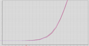
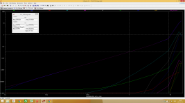
I'm going to use Toshiba fets for the current sources simply because I have them. Playing around with ltspice suggest This amp would really like higher bias currents alot.
4A => 0.035% THD @ 1W, 1kHz
6A => 0.012% THD @ 1W, 1kHz
I figure the sinks Im going to use are good enough for 150W/ch even tough The fets will be mounted somewhat non ideal towards the back of the enclosure.
I'll have the current sources on one side and the differential pair on the other (separate sinks) If i lower the common mode voltage (im only ever going to use it with balanced drive) I should be able to have 50/50 division of the heat.
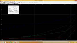
Attachments
- Home
- Amplifiers
- Pass Labs
- Firstwatt F1J