wow ! hold your horses
ZM educating someone - that's certainly hilarious
solder joints are messy
wiring is messy
NTC soldered directly to mains socket and switch ; you can do the same - but you must extend NTC leads and dress them in proper silicone insulation
bare mains contacts on both switch and IEC socket
anyway ...... everything is just sloppy
take your time - search for pictures ( and there are plenty of them ) of decent made amps and you'll see what is wrong there and how to make it in proper way
Mr. TR deserves not just funny note from Papa's lawyers ( not because he can take part of Papa's pie , but because these poor "amps" are negative propaganda for Papa's work) , but also not just one lawsuit because his "amps" are jeopardy
I'm service tech my entire professional life ..... and that's just disgrace for our craft

I agree as to how insulting it is business wise, I was wondering "build wise" Thanks for the lessons!
Russellc
lessons ?

OK - here is most important one :
1. relax
2 . learn
3. build
4.enjoy
5. learn
6. build
7. enjoy
those steps - mix them , shake them , mutate them in every possible way
😉
OK - here is most important one :
1. relax
2 . learn
3. build
4.enjoy
5. learn
6. build
7. enjoy
those steps - mix them , shake them , mutate them in every possible way
😉
Excuse me if I bring this back up (holy thread resurrection FTW), but there's either something wrong in my search methods or a lack of PCBs/parts sources for this project.
In fact, after a long time deciding what to do next, I ended up with the conclusion that turning my F4 in an F1J would be interesting for both my speakers and my preamp (which was being pushed really too hard to reach satisfactory SPLs).
One initial idea was to build a Pumpkin preamp, but I ultimately found more entertaining to try a transconductance amplifier. Plus, my Audible Illusions Modulus 3A preamp is a good toy and it's got a good phono section, which I need.
Could anybody point me to a source for PCBs and matched parts?
Thank you,
Giacomo
Will a F1J be able to drive a true ribbon tweeter directly without transformer or will it show clouds of white smoke? Impedance is nearly zero Ohms, it's a simple aluminium foil.
clever way of making amp for ribbons is - to make amp with small PSU voltage ;
small , but still adequate for linearity of active devices used ;
always look at that thing ;
if that criteria isn't fulfilled ........
small , but still adequate for linearity of active devices used ;
always look at that thing ;
if that criteria isn't fulfilled ........
Giacomo,
I have a set of F1 boards I got from Suds GB I have not used (got sidetracked into an F5,suits my speakers better)as well as some matched irfp240/9240...
PM me if you are interested.
Regards, Elwood
I have a set of F1 boards I got from Suds GB I have not used (got sidetracked into an F5,suits my speakers better)as well as some matched irfp240/9240...
PM me if you are interested.
Regards, Elwood
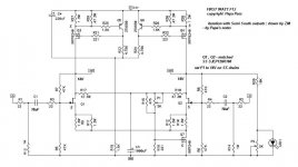
Thanks. That looks better than my hand-drawn schematic.maybe this will be useful to someone
just found it in my FW folder
But it still leaves some questions. The original F1 schematic shows adjustment voltages of 7 V on the gates of the main power FETs, and 3 V on the gate of the Aleph current source. Your F1J schematic has nothing there.
It makes sense that the JFET gates might have a completely different voltage. The F1 has a 60% resistor voltage divider, and the revised F1J has a 50% resistor voltage divider. I assume the drains of the F1 FETs were around 12 V if there was 7 V on the gates (just roughly calculating from the voltage dividers only). If we read Papa correctly that the drains are bumped up to 14 V, as your schematic shows, then the 50% dividers would leave the gates at the original 7 V.
Would you think that the Aleph current source gate bias voltage should remain at 3 V?
these values are by Papa's words somewhere around ;
I didn't checked
whatever - circuit is mostly self adjusting - all you need is to fiddle with P1 ( to set where Da Man sez it need to be ) and to read basics more
tip - his papers at FW will tell you more than I can , in a life-time .
I didn't checked
whatever - circuit is mostly self adjusting - all you need is to fiddle with P1 ( to set where Da Man sez it need to be ) and to read basics more
tip - his papers at FW will tell you more than I can , in a life-time .
Just 1 thing. Is that an Aleph CS?
nope - plain Papatype mosfet CCS(es)
there is no modulation of them
Are you asking about the common current source at the bottom, or the dual current sources at the top?Just 1 thing. Is that an Aleph CS?
I thought the current source on the bottom might be an Aleph. Note how the output voltage is fed to the gate of the current source FET. This is a form of feedback to maintain the voltage on the high side. But every Aleph schematic I've seen involves a bipolar transistor as well as the primary conducting FET. The Aleph patent doesn't seem to show the exact same circuit. Regardless of what it's called, you'll find Nelson Pass discussing this common current source in Zen Variations 7.
The dual current sources at the top are most certainly Aleph current sources.
Yes that is FB but it is only to maintain the LTP current source. It monitors the output DC voltage as a refrence to drive the CS. If the output goes up in DC Voltage, to little current must be present so it drives more etc. There are nno Aleph's in this circuit.

I guess I should explain a bit more. The Output CS's are "Typical" and do not include the summing of an output current signal with the CS sense signal as does Aleph. There would need to be a method of sensing the output current and sending that signal to the CS. That portion is absent. A "typical" current source.
Oh! You're absolutely right! I had a bunch of hand-drawn circuits on the same page, and only some of them were Aleph current sources. I did not look closely enough at the F1 schematic to see that it was different from the Aleph. You're correct that the upper current source pairs in the F1 and F1J have no control inputs at all.I guess I should explain a bit more. The Output CS's are "Typical" and do not include the summing of an output current signal with the CS sense signal as does Aleph. There would need to be a method of sensing the output current and sending that signal to the CS. That portion is absent. A "typical" current source.
So I retract my earlier statements.
The upper pair of current sources are plain, unmodulated current sources - the epitome of a constant current source. The common current source at the bottom is modulated by feedback, so it is not a constant current source, but it also is not a patented Aleph current source.
The botom CS actually sums + out and -out together (Null) to form a DC output level. There is filtering going on also so any distortions hopfully get lost in the filter...
Although it is FB it is probably rolled off to only a few Hertz.
Although it is FB it is probably rolled off to only a few Hertz.
Thread resuscitation...
OK, I’m new to this (both DIY audio and Pass designs). I am currently building large open baffle speakers using Lowther full range drivers. I have deliberately kept things simple for my first project using kit circuits from Twisted Pair Audio for dac, linestage and amps.
Before I have even finished my first build, the urge to tinker has struck. While waiting for the current batch of goodies to arrive in the post, I have been reading about the First Watt amps and am particularly intrigued by the idea of the F1(J). Balanced single-ended, class A and current output all sound like good ideas, but importantly the low damping should match very well with the Lowther DX4s and give them a bit more life.
What I can’t work out is if the F1, with the mods for JFET detailed earlier in this thread, is the latest thinking on this design. Has it been superseded by anything? Are any of the Zen series balanced single ended class A transconductance designs?
Basically, are there any other designs I should be looking at?
If this is the best design to start with, I will have to think about modifying the power supply or circuit to use my existing pair of 24-0-24v 500VA transformers from the TPA amplifiers. Could we do anything clever with ±30v DC supply rails? I don’t see how with the speaker output floating at 13.8v DC above ground.
Lastly, I presume since the circuit is published in the service manual and in the public domain there is no issue using it for DIY even though it is under copyright and patents.
- Home
- Amplifiers
- Pass Labs
- Firstwatt F1J