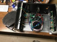
Yeah! It is working🙂. With some temporary wiring in place I have powered up one channel and it is working nicely. The voltages shown on the schematic and in the write up are matching well, except the gate of Q1 and Q2 is running at 7.96 VDC relative to ground versus the listed 7 volts. The speaker outputs are at 13.8 VDC and the DC offset between the outputs is ~6mV. I used an F4 transistor kit from the diyAudio store to get the matched transistors, and based on the low DC offset produced I am quite impressed with the matching of these transistors. A sound check with a beater speaker and an old iPod sounds pretty good. I am satisfied that all is well with the boards, and I am comfortable selling the remaining boards. In the next couple days I will PM those who have expressed interest to get address information to calculate shipping. The boards will be $20 + shipping for qty(1) power supply board and qty(2) amp boards.
Attachments
So I had written off the possibility of building anything with the SemiSouth JFETs, due to their unobtanium status, but I stumbled on this:
SemiSouth JFET Transistor SJEP120R100 High Performance Audio Amp New Matched x 2 | eBay
What does anyone think? Are they legit? The seller has very good reviews and feedback left specifically for the JFETs.
SemiSouth JFET Transistor SJEP120R100 High Performance Audio Amp New Matched x 2 | eBay
What does anyone think? Are they legit? The seller has very good reviews and feedback left specifically for the JFETs.
There was some discussion on this seller's listings last year:
SJEP120R100 on ebay: are these the real thing?
Please be advised that they are only 'matched' in lot code.
SJEP120R100 on ebay: are these the real thing?
Please be advised that they are only 'matched' in lot code.
I would be cautious as the markings and package in the photo do not
match my inventory.

That is very good to know! Thank you, thank you for looking at the listing!
Hi Chas, thanks for the boards again. I had a little time yesterday, so I put it all together. It works from the first moment. I am using variac, test speakers with cap, and fans to cool it down in the first testing stage. Its just test layout on the carpet at this moment. Case work will have to wait. I adjusted drain voltage no problem, it draws current as expected. I have small dc (0.60 and 0.45 V) on the output which I will address once it is settled after some run time. I am using cap before test speakers right now. It sounds nice so far.
Thanks Nelson for sharing the circuit and the outputs!
Thanks Nelson for sharing the circuit and the outputs!
Wow adason that was a quick build! Glad to hear your amp is alive and well, thanks for posting your progress! When you get it cased and presentable I would love to see some pictures.
I addressed the dc offset. Added 150k and 180k resistors to R105. That took dc from half the volt positive to 50mV negative. Instead of fiddling with those resistors again, I added 2M2 resistors on opposite side, R106. Offset is -11mV at start, as it heats up, it goes across zero to positive and stays ~20 to 30mV, depends how much I blow the fan on it.
If I knew, I would order another pair of ideal bridge rectifiers, to avoid some heat. This amp heats a lot. I may run it at slightly lower voltage. I do not like it hot. Some do 🙂
Otherwise it sounds great.
If I knew, I would order another pair of ideal bridge rectifiers, to avoid some heat. This amp heats a lot. I may run it at slightly lower voltage. I do not like it hot. Some do 🙂
Otherwise it sounds great.
I agree this amp makes a lot of heat, I have not compared the actual power dissipation, but it feels about as hot has my BA3.
You obtained good results using the trimming resistors. I will look into adding a potentiometer in series with R105/R106 to make this easier on future boards.
BTW all of the boards that I had are now sold. I plan to make a few small improvements (feedback/suggestions are welcome) and make another small order for people who have expressed interest, or possibly try a group buy.
Trimmer in that position is a good idea. If you make new boards, I would be interested in a set, to make F1.
Has anyone tried switching power supply on F1 and F1J? It would make sense since it runs on non symmetrical supply.
Has anyone tried switching power supply on F1 and F1J? It would make sense since it runs on non symmetrical supply.
Hi Chas,
I would definitely be interested in a set of boards - have also sent you a PM, thanks.
I would definitely be interested in a set of boards - have also sent you a PM, thanks.
UMS Board Schematic
I have had a request for the schematic for the UMS boards, so I am posting them here. As expected they are pretty much the same as the FirstWatt schematic, with the addition of the trimming resistors, dedicated pads for various input capacitor configurations and the power indicating LED circuit has been moved to the power supply board using a single fixed resistor rather than the potentiometer of the original.
PS: Sorry about the smudges on the power supply schematic, I'm not sure what the kids got on the scanner.
Attachments
Last edited:
Build so far
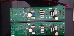
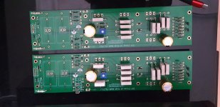
Here are a few photos of my boards and the case i shall be using still waiting on some parts from mouser.Hopefully next week can continue the build of this f1j amplifier Again thanks to csample for releasing his version of the board .As well as thanks to Mr Pass for his designs .
Here are a few photos of my boards and the case i shall be using still waiting on some parts from mouser.Hopefully next week can continue the build of this f1j amplifier Again thanks to csample for releasing his version of the board .As well as thanks to Mr Pass for his designs .
Attachments

- Home
- Amplifiers
- Pass Labs
- Firstwatt F1J