I finished the phono stage chassis, will try my Ortofon with standard gain and see what happens. If the gain is too high, then I will try setting it up for 45dB with rotary switch.
Now on to the power supply:
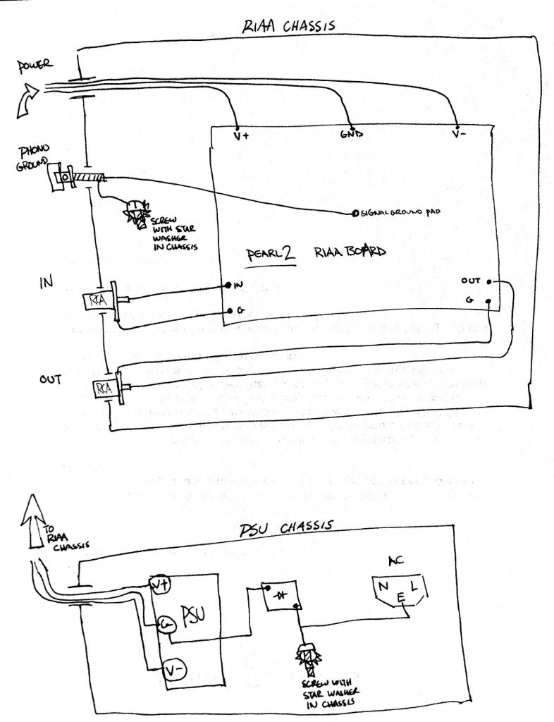
In Wayne' schematic, look like the purpose of the 35A bridge rectifier is to isolate the earth ground from the signal ground? So if I build the power supply in separate chassis, then maybe I do not need this 35A bridge, and I can just hook up the wall earth to the chassis with a wire?
My power supply ground will be floating in the PS chassis, and grounded together with the PCB star ground in the phono stage chassis.
Please let me know if this will work. Thanks all.
Now on to the power supply:
In Wayne' schematic, look like the purpose of the 35A bridge rectifier is to isolate the earth ground from the signal ground? So if I build the power supply in separate chassis, then maybe I do not need this 35A bridge, and I can just hook up the wall earth to the chassis with a wire?
My power supply ground will be floating in the PS chassis, and grounded together with the PCB star ground in the phono stage chassis.
Please let me know if this will work. Thanks all.
In your diagram, looks like you only connect two terminals on the 35A bridge? So for this orientation the wall earth connects to the (~), then the (-) connects to the chassis? Or, the wall earth to (+), then the (~) to the chassis?
And you leave the other two terminals on the GBPC unconnected?
Thanks!
And you leave the other two terminals on the GBPC unconnected?
Thanks!
In your diagram, looks like you only connect two terminals on the 35A bridge? So for this orientation the wall earth connects to the (~), then the (-) connects to the chassis? Or, the wall earth to (+), then the (~) to the chassis?
And you leave the other two terminals on the GBPC unconnected?
Thanks!
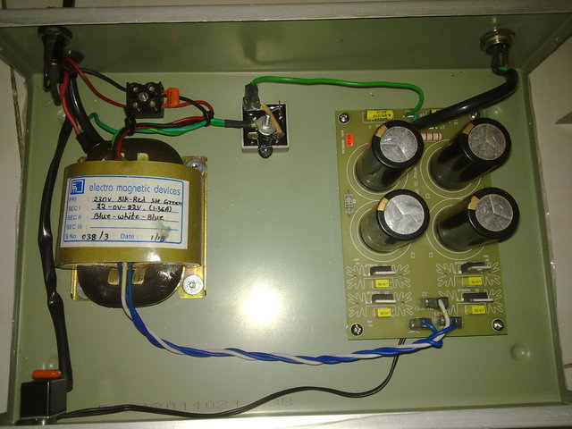
Look here -

Wire ending in the central bolt of 35A bridge block is coming from mains IEC socket. The wire with sleeve on connector is coming from PS ground. Just connect diagonal pins of bridge blocks together. Both the connecting wires are isolated from each other. One connection connects to chassis and IEC earth ground from mains together. Another connection goes to PS output Ground.
PS: in above diagram there is one 10Ω, 10A NTC (black part on the bridge block ) which could be safely omitted. But I kept it there to help bridge block (in case catastrophe).
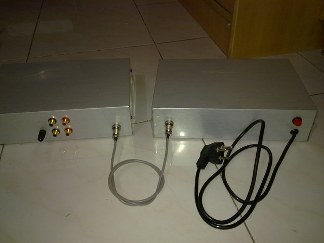
Another example from my build is here -
In two chassis construction isolation bridge or resistors, thermistors etc. are not necessary. Mains safety earth should be directly connected to power supply enclosure . Signal ground is connected to audio circuit chassis.
Purpose of isolation bridge or any isolation device is prevent hum induction in audio ground. Audio component with the highest signal level, like power amp or headphone amp should have direct connection between mains earth and audio ground. All others should have no connection, if it is dual chassis approach, or some form of isolation between signal and safety earth if use single enclosure.
Two or more directly earthed components will produce hum, while avoiding only one component with direct link between signal and mains safety earth will produce buzzing. Transformer should be of split bobbin construction or should have electrostatic screen tied to mains earth if toroid.
It was recommended by well known audio expert Ben Duncan a long time ago and is well proven in practice.I always have hum and buzz free reproduction using this method. Some factory made power amps have isolation between audio gnd. and safety earth. Remove it and make direct link. Same for the headphone amps.
Your approach is same as used in Pass two chassis preamps and phono preamps. Good, but could be simpler . In this case, DC connector case shouldI kept both the chassis - PS and Pearl 2, grounded to earth. Same time PS, DC ground was kept floating and connected to mains through isolator at only one place. DC ground never connected to chassis and same was supplied to tonearm ground.
be in good electrical contact with both chassis. I have never seen another preamp using that Pass Lab approach.
You must isolate grounding post from audio circuit chassis and tie it to audio ground.
Your approach is same as used in Pass two chassis preamps and phono preamps. Good, but could be simpler . In this case, DC connector case should
be in good electrical contact with both chassis. I have never seen another preamp using that Pass Lab approach.
You must isolate grounding post from audio circuit chassis and tie it to audio ground.
Yes, agree. That is how I used 3 core wire with additional shield. Additional shield connects shell of connectors and thus both the chassis. 3 cores carry +33, 0 and -33 to Pearl 2 board. And connection is highly secured.
My Pearl two finally finished.
When trying to adjust P1, voltages from both boards oscillate around +/- 35mV.
Seems like I am having problem with the left board. It is very quiet, but whenever I touch the body of the RCA interconnect (or wiggle the interconnect cable), this channel always get a loud hum. Swapped the cables around and determined it was not cable issue (it is always the left board; right board never have this problem).
I removed C7 on both boards, and R15 has jumper on it.
Any suggestions for troubleshooting? Are there some voltages I should check on the board?

Okay - I figured out what the problem is. But first thing first, the voltages:
R9: 20.2V (measured 20.08V)
Q3/Q7: 9.4V (measured 8.8V)
R8/Q3: 10V (9.45V measured)
R24: .04-.01V (measured .05V)
Q10: -23V (measured -22.5V)
R28/C24: -24V (measured -23.7V)
R6: 1.5V drop across R6 (1.75V measured)
Q11/R29: -23V (-22.5V measured)
Some voltages are not exactly the same as in the spec, but both channels pretty much measures the same with each other.
Now about the hum:
It turned out to be an interconnect issue. I was using Audioquest IC between turntable and Pearl, and the right channel hummed very loud whenever I touched the Audioquest RCA connector. For some reason, the hum only happens on one PCB.
Then I tried switching the interconnect to cheap ones (the one that usually comes with cheap DVD players). Hola! - the problem is gone. Now I can only hear hums from both channels when the volume level is very high.
I do not know what the problem is with the AQ interconnects.
Another interesting fact: When I unplugged the interconnect between Pearl and my preamp, there is still hum from both channels!!! I think this proves that the hum does not come from Pearl's active circuit. Perhaps the interconnect acted like antenna.
At this point, I will call the PCB's good, the hum is about the same level as the noise coming from my tube preamp. Time better spent catching some sleep and listening to records.
Questions:
1. Is your build 100% quiet, or do you still hear hums at high volume positions? Does the hum gets a little louder with preamp volume?
2. What kind of interconnect do you use to connect turntable and Pearl?
- Home
- Amplifiers
- Pass Labs
- Pearl Two