post238, correctly shoows the wiring of more than 2channels through to the B! input.
Note however, that the ground wire from the input sockets must follow the exact same route as the 3 Hot inputs, then pass close by the selector switch and again follow exactly the Hot line to the B1 input pad. This is to minimise the loop area of the inputs that the B1 will read and pass on to the next stage.
Note however, that the ground wire from the input sockets must follow the exact same route as the 3 Hot inputs, then pass close by the selector switch and again follow exactly the Hot line to the B1 input pad. This is to minimise the loop area of the inputs that the B1 will read and pass on to the next stage.
Ok , the selector between RCA input and board , board to Pot , pot to board ,then to output ?
left to one side of selector , right to the other - Bottom solder pins are L & R out put to board soldered in to L 1 & R 1 ..... CW ... I don't Waylon and Willy ,do I need to connect this ?
Rich
left to one side of selector , right to the other - Bottom solder pins are L & R out put to board soldered in to L 1 & R 1 ..... CW
... I don't Waylon and Willy ,do I need to connect this ? Rich
The Pot connects only to the board. The board has all the traces in it to let the pot interact with the rest of the circuit.
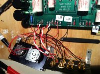
The input RCA jacks need to be wired to the selector switch, thence to one set of inputs (choose either set 1 or 2) and then the jumper needs to be added on the board.
This photo might help -
The input RCA jacks need to be wired to the selector switch, thence to one set of inputs (choose either set 1 or 2) and then the jumper needs to be added on the board.
This photo might help -
An externally hosted image should be here but it was not working when we last tested it.
Banned
Joined 2002
The Pot connects only to the board. The board has all the traces in it to let the pot interact with the rest of the circuit.
The input RCA jacks need to be wired to the selector switch, thence to one set of inputs (choose either set 1 or 2) and then the jumper needs to be added on the board.
This photo might help -
An externally hosted image should be here but it was not working when we last tested it.
great photo, where did you buy your psu board ?
The PSU board is Peter Daniel's 'Universal PSU' board, which is completely incredible in it's versatility.
Let me do a little cut 'n paste here to give you good information - -
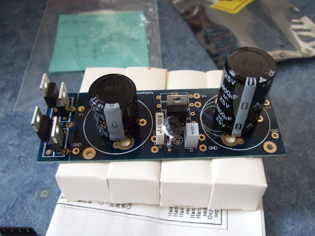
Here is the single-rail universal power supply PCB from Peter Daniel. It's a very nice board, with the ability to choose 2- or 3- pin diodes (or none at all), many different lead spacings on the filter capacitors, and either a LT1085 or LM317 regulator. Shown here are MUR680 diodes and a LM317 regulator.
Circuit board - Universal Power supply PCB from Peter Daniel AUDIOSECTOR This product is not on his website, but email him and he takes care of it quickly.
Lots more info on this board here - http://www.diyaudio.com/forums/audio-sector/149672-universal-power-supply-pcb.html
Let me do a little cut 'n paste here to give you good information - -
Here is the single-rail universal power supply PCB from Peter Daniel. It's a very nice board, with the ability to choose 2- or 3- pin diodes (or none at all), many different lead spacings on the filter capacitors, and either a LT1085 or LM317 regulator. Shown here are MUR680 diodes and a LM317 regulator.
Circuit board - Universal Power supply PCB from Peter Daniel AUDIOSECTOR This product is not on his website, but email him and he takes care of it quickly.
Lots more info on this board here - http://www.diyaudio.com/forums/audio-sector/149672-universal-power-supply-pcb.html
Hi All ,
never fails ... company all day ! shouldn't have answered the phone LOL .
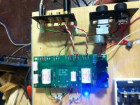
Soldered outputs .
OK , I have jumped Input 2 as per 6's version . Wired input switch ... Changed grounding
wire . I have ganged all ground pins on RCA plugs to one green wire . That connects to G on the PCB ?
I have soldered none of these connections till I get the all clear .
What gets wired to L1 & R1 ?
BTW 6 ... I need to get the reg and wait for the caps from Germany for PSU
never fails ... company all day ! shouldn't have answered the phone LOL .
Soldered outputs .
OK , I have jumped Input 2 as per 6's version . Wired input switch ... Changed grounding
wire . I have ganged all ground pins on RCA plugs to one green wire . That connects to G on the PCB ?
I have soldered none of these connections till I get the all clear .
What gets wired to L1 & R1 ?
BTW 6 ... I need to get the reg and wait for the caps from Germany for PSU
Attachments
Last edited:
The wires from the selector switch can be taken to one or other of the input connection on the pcb and then a jumper soldered between the appropiate solder pad and the centre 2 pads of the six near the front of the board. Otherwise just run the wires to the centre 2 solder pads of the six.
6L6 beat me to it.
6L6 beat me to it.
Too late ... its welded good ...
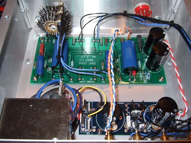
Now , the ******* Pot .. ! I know others have used the Alps Blue Velvet ...
back to trawlin the posts ! or someone could help ?
R
KKKK , Just got this link . Can anyone help converting these letters to whats on my board please .
Maybe the Bryston can have an early night and a few days off !
http://www.hificollective.co.uk/pdf/alps_layout1.pdf
Last edited:
17th December 2008, 04:02 PM
#1010
Join Date: Mar 2001
Most likely In = CW, Out = Wiper, Ground = CCW
The pot is the easiest of them all. It does not matter what orientation you have the pot in, if you are holding the shaft and the body is behind, counter clockwise ('anti-clockwise' in the Queen's English, I believe...) is always the same side.
So... With the shaft pointing towards you, put the left most pin to "CCW", the middle to "W" and the right most to "CW". There are two decks in a stereo pot, so one of them is left, and the other is right. Which is which doesn't matter, just don't have any connections common to the separate decks.
So... looking at your linked photo,
IP to CCW
OP to W
Earth to CW
That's what I was thinking. My confusion is in the splitting of the input. It seems that splitting the input is not cool. Putting the attenuator at the end of the buffer also seems to mess up the buffer circuit but solves the two output situation. You say add a switch or two... where are you thinking?
Thanks,
39°f and cloudy in MN
Thanks,
39°f and cloudy in MN
I need to look at some schematics I have somewhere. (Which is to say, hopefully I can find them...)
But basically you would have your selector switch, and then 2 'outputs' from that switch, one to a 'normal' B1, the other to the 'tape' B1, which would have no attenuation and it's own outputs. (Tape out)
But basically you would have your selector switch, and then 2 'outputs' from that switch, one to a 'normal' B1, the other to the 'tape' B1, which would have no attenuation and it's own outputs. (Tape out)
Not wishing to be a " knowall " looking at the back of the board ccw is the ground ... I reversed o/p and I\p and got a backwards pot ..... LOL . Sorry 6
I got something right
I still have one channel down . Can anyone help with trouble shooting this ?
All solder joints and cables are good so, Looks like something in the board .
There are no voltage checks on the schematic that I can see - its beyond my skills to work them out on my own .....
thanks again ,R
- Status
- This old topic is closed. If you want to reopen this topic, contact a moderator using the "Report Post" button.
- Home
- Amplifiers
- Pass Labs
- B1 builders thread