jean-paul said:It is quite comical to see ....questions about the normal version arise in this thread
No its not
But thanks anyway, for a proper answer
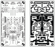
Hi, I could organise something like that but IMO the PCB still is not fully finished but maybe I am too demanding. I would like to see the rectifiers moved to the upper left corner where the transformer is normally located and that inputs and outputs find a more practical place. So outputs at the back of the PCB/case and inputs at the front/volume potentiometer side. IMHO the muting relay should be there and I would not mind to have the volume potentiometer and 4 source relays on the PCB as well.
As can be concluded from the comments the shunt supplies are much better than 317/337 regs so this was a big step in the right direction. I won't argue about higher power consumption anymore
As can be concluded from the comments the shunt supplies are much better than 317/337 regs so this was a big step in the right direction. I won't argue about higher power consumption anymore
Here is a small tip to reduce noise further in this circuit :
With input signal grounded and well matched FETs, the circuit is essentially two identical current sources connected to both rails and the output.
However, change in Vds (e.g. due to supply rail noise) also causes a slight change in Id, be it much less than change in Vgs. If, however, noise from both rails is symmetrical about ground, they induce the same Id change on both JFETs, and hence cancels mutually with no effect on the output.
How can that be implemented ?
Use a single power supply, say 30V, the positive of which connected to the positive rail, and the negative to the negative rail. Create an active ground by a voltage divider using two equal resistors (e.g. 10k). Connect the tap point of the divider to an opamp, and use the output as ground. Now you have a PS of +/-15V.
Most opamps can deliver 20mA with ease, so there is no problem with current delivering capabilities.
You'll be amazed how quiet it can get.

Patrick
PS Not my invention. I stole the idea from tubecad.com
With input signal grounded and well matched FETs, the circuit is essentially two identical current sources connected to both rails and the output.
However, change in Vds (e.g. due to supply rail noise) also causes a slight change in Id, be it much less than change in Vgs. If, however, noise from both rails is symmetrical about ground, they induce the same Id change on both JFETs, and hence cancels mutually with no effect on the output.
How can that be implemented ?
Use a single power supply, say 30V, the positive of which connected to the positive rail, and the negative to the negative rail. Create an active ground by a voltage divider using two equal resistors (e.g. 10k). Connect the tap point of the divider to an opamp, and use the output as ground. Now you have a PS of +/-15V.
Most opamps can deliver 20mA with ease, so there is no problem with current delivering capabilities.
You'll be amazed how quiet it can get.
Patrick
PS Not my invention. I stole the idea from tubecad.com
Yeah, that seems way simpler than that shunt supply stuff. Couldnt you even just use TLE2426 as here: http://tangentsoft.net/elec/vgrounds.html , or does the symmetrical B1 need more than 20-40mA?
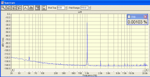
See attached, the noise floor relative to 0dB=1VRMS calibrated, and THD of my P2P symmetric. I don't see why I would want to put an op amp in the psu to imitate ground so to chase noise further. What noise? With shunts, it sounds even better.
Virtual ground via divider, exists in normal B1 with extra input RC filtering BTW.
Virtual ground via divider, exists in normal B1 with extra input RC filtering BTW.
Attachments
> Virtual ground via divider, exists in normal B1 with extra input RC filtering BTW.
Yeh, I wonder why. And I thought you want to get rid of the coupling caps ??
> I don't see why I would want to put an op amp in the psu to imitate ground so to chase noise further.
Your choice.
This circuit, especially with split rails, came from JC decades ago. I have been using various versions for at least the last 5 years, with 2SK170s, BF862s, LU1014s, ...., using batteries, Walt Jung regs, shunt regs, ....... you name it.
http://www.diyaudio.com/forums/showthread.php?s=&threadid=140488&highlight=
http://www.diyaudio.com/forums/showthread.php?s=&threadid=128571&highlight=
http://www.diyaudio.com/forums/showthread.php?postid=1592820#post1592820
http://www.diyaudio.com/forums/showthread.php?postid=1130743#post1130743
Patrick
EUVL said:[B
Your choice.
This circuit, especially with split rails, came from JC decades ago. I have been using various versions for at least the last 5 years, with 2SK170s, BF862s, LU1014s, ...., using batteries, Walt Jung regs, shunt regs, ....... you name it.
Patrick [/B]
I never add circuitry when there is no pressing need. Your proposal is functional, I don't doubt it, but I prefer not to fix what is not broken in the first place. Thanks Patrick.
If I may add, it also depends on what you build the buffer for. If you're buffering a headphone amp or a gainclone then you can power the buffer and the rest with a dual regulator like salas' shunt. You can get a stiff psu with low output impedance and low noise that way if you're careful about details. But sure, for something portable, a virtual gnd circuit does make sense; it's all about trade-offs in the end.
Just my 2c.
Just my 2c.
Please wait some more, La Ode will add some functionality to this shunt version. I asked him if he could move the power supplies to the left to avoid ground jumpers and make input and output wiring simpler. He replied that he will change the PCB but it will take some time.
thanh1973 said:I just noticed right and left channel input share the same ground point.
Is this the preferred way of doing things?
Really
I thought it was one channel only

Well, I would like that
I also like double bridge in supply
btw, whats that with the snail ?
Ahh, got it
I thought it was symmetrical, like in balanced
Its symmetrical supply
Right
That feels much better now
thanh1973 said:Hi Salas could you give us the dimensions of the pcb?
Are they the same as the original with linear regs?
By the way if we can get an order of 100 boards then I can get them made for $5 (US dollars) each + postage costs.
If you print it out at 124X62mm the Mosfets and Transistors / JFETs pitches look right. I did and compared with the actual semiconductors. The filter caps pitch looks smaller than 4700uF snap in that I compared. But there is pad space to drill wider. Maybe Crt used straight long pin filter caps. I emailed him to give us the intended dimensions. If you want the high resolution files and Eagle files, email me. Jean Paul wants something arranged differently, don't know about that. Me I find the current one practical enough.
tinitus said:btw, whats that with the snail ?

I can see that Crt likes System Of A Down. Plus Malakian's short lived assortment ''Scars On Broadway''. About the snail, he is the one to tell us the symbolism if he likes.
Attachments
- Home
- Amplifiers
- Pass Labs
- Building a symmetrical PSU B1 buffer


