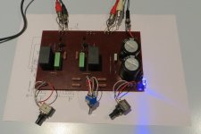
I suppose a few pics are in order to give you guys an idea of how I've done my B1. All caps are Vishay (and one Ero) except for the two big electrolytics.
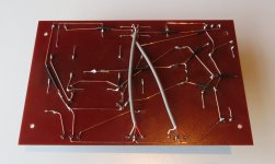
The board is Paxolin and test points were used as solder points. The lid is not done yet.. And I may also add a 4mm alu front panel with etched lettering.
The first picture was taken after final testing and before mounting the board in the enclosure.
The board is Paxolin and test points were used as solder points. The lid is not done yet.. And I may also add a 4mm alu front panel with etched lettering.
The first picture was taken after final testing and before mounting the board in the enclosure.
Attachments
I suppose a few pics are in order to give you guys an idea of how I've done my B1. All caps are Vishay (and one Ero) except for the two big electrolytics.
The board is Paxolin and test points were used as solder points. The lid is not done yet.. And I may also add a 4mm alu front panel with etched lettering.
The first picture was taken after final testing and before mounting the board in the enclosure.
Skylar88 your B1 diy work is fabulous

Build another in your Paxolin style !!!!
Thanks for educative show 🙂
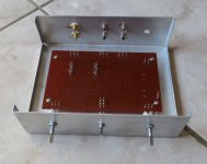
Probably a bit of in rush current to deal with on the 15000uF caps.I have finished building a B1 and it sounds great. For the board I have used Paxolin with 0.8mm copper wire for point to point connections. It's housed in an aluminium enclosure.
My thanks go to Nelson Pass for the design. I'm grateful for the generous help from the forum members who answered my questions, and I'm also indebted to forum member Twocents who let me listen to his B1 and encouraged me and gave advice when I needed it. It really helps to have a partner in this type of crime. 😀
I still have a question, though... If the current draw is only about 20 milliamps, then why does R1 need to have a rating of 3W? Wouldn't a 1W resistor be sufficient?
Thanks in advance.
Christo

Probably a bit of in rush current to deal with on the 15000uF caps.
Hmm ok, that could be a valid reason. But for how long can the in-rush be? Certainly not long enough to require 3W! But I will experiment and measure the temperature with a 1W. I have a 5W on there now, because I couldn't find 3W.
C*R tells you the RC time constant.
The capacitor is charged to just over 60% of final voltage in one RC time period.
In five RC time periods it is nearly fully charged.
15mF = 0.015F
R = 1ohm
5*RC = 0.075seconds.
The capacitor is nearly fully charged in 0.075seconds.
The capacitor is charged to just over 60% of final voltage in one RC time period.
In five RC time periods it is nearly fully charged.
15mF = 0.015F
R = 1ohm
5*RC = 0.075seconds.
The capacitor is nearly fully charged in 0.075seconds.
The capacitor is nearly fully charged in 0.075seconds.
Thank you AndrewT. Then it doesn't make sense that R1 needs to be 3W, or even 1W. I have not calculated temperature increase because I can't find the thermal coofficients in the Vishay datasheet.
Maybe Nelson Pass was just playing very safe by specifying a 3W resistor! Or maybe there is another reason?
you need to consider the instantaneous power dissipation at the moment of start up.
If you think the resistor will behave like an instantaneous fuse, then you may find that even 3W is too small !
B.Putzeys did this for his power input resistors and came up with expensive melfs as the only small way of getting reliability inside the package.
If you think the resistor will behave like an instantaneous fuse, then you may find that even 3W is too small !
B.Putzeys did this for his power input resistors and came up with expensive melfs as the only small way of getting reliability inside the package.
Good point Andrew. One of the things with the B1 is that the PS could be anything. depending on how much current the PS it is hooked up to can deliver the resistor may very well be strained at startup even with a 3W.
The very large cap will appear like a short at initial startup. If our PS can say deliver 1A continuous current then we will have roughly 18V (assuming 18V supply as per the original design) drop across the resistor and therefore a short term power dissipation of around 18W!
Looking at a random Vishay 3W 1 ohm restistor http://www.farnell.com/datasheets/2...2.2095250819.1503910736-1953168152.1503910736 we see that short term overload is only 5 X rated.
Take into consideration as well that the rated wattage starts dropping for ambient temperatures above 25 deg C and you could well end up with cooked resistors if the device is switched on and off regularly.
Tony.
Take into consideration as well that the rated wattage starts dropping for ambient temperatures above 25 deg C and you could well end up with cooked resistors if the device is switched on and off regularly.
But with the capacitor being fully charged in 0.075seconds, heat is hardly a consideration. So, I'm not going to worry about it anymore. I guess both 1W and 3W would work fine.
Christo
Last edited:
you need to consider the instantaneous power dissipation at the moment of start up...................
.................
Looking at a random Vishay 3W 1 ohm restistor http://www.farnell.com/datasheets/2...2.2095250819.1503910736-1953168152.1503910736 we see that short term overload is only 5 X rated. ..................
I forewarned and gave a B.Putzeys' example.But with the capacitor being fully charged in 0.075seconds, heat is hardly a consideration. ..............
Wintermute went to the bother of finding instaneous overload data and quoting it here.
Yet you come up with "heat is hardly a consideration"
What nonsense !
The least you can do is some experiments on lifetime for repeated cold starts before coming to any conclusion. Just ignoring the advice and data is non engineering.
Duly noted, Andrew. Thanks for the warning. I based my logic on knowledge in a different field and obviously, things are different in electronics than it is in electric motor design where heat can be calculated quite accurately - and where heat is the main enemy of components. Let's get back to enjoying the B1... 😉
Christo
Christo
A basic question,came up on working with my BF862 design. What is the role of R102 AND R202 in B1?
https://www.passdiy.com/pdf/B1%20Buffer%20Preamp.pdf
My design here with a better PS.
Super Regulator
POST# 1388
I am using gate resistors with bf862 and put the bias voltage before the gate resistor and skipped the 1K (R102 and R202).On LT spice sim one without 1k in looks better in terms of THD by 10 times more(0.0089% vs 0.011%).
Last edited:
They are there to bleed off DC from sources which are capacitively coupled
so that you don't get thump when switching. You can ignore them.
so that you don't get thump when switching. You can ignore them.
Aren't the 1k R102 / R202 there to prevent oscillation and the R101 / R201 to prevent thumps when switching inputs?They are there to bleed off DC from sources which are capacitively coupled
so that you don't get thump when switching. You can ignore them.
Papa,The 1K are not directly connected to ground. Did you mean R100,R200,R101 ,R201 as bleeders?They are there to bleed off DC from sources which are capacitively coupled
so that you don't get thump when switching. You can ignore them.
I was probably looking at another version of the schematic. Usually I have
lots of them laying around in the folders and often they only vary by part #.
The big ones are the bleeders, the 1k or so are for parasitic oscillation.
lots of them laying around in the folders and often they only vary by part #.
The big ones are the bleeders, the 1k or so are for parasitic oscillation.
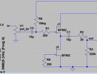
Papa,this is how I made it. Simulating without any difference. is this ok?
Attachments
Last edited:
Have you read D.Feucht's paper on the jFET Follower?Papa,this is how I made it. Simulating without any difference. is this ok?
Attachments
- Home
- Amplifiers
- Pass Labs
- B1 Buffer Preamp