A 20VA tarnsformer rated for 20Vac has a rated secondary current of 1000mAac.
It will be able to run continuously into a 20ohms resistor.
If you attach a capacitor input filter after the bridge rectifier then you must de-rate the transformer for that duty.
Expect somewhere around 50% to 60% as the de-rating factor.
The maximum continuous DC current will be around 550mAdc.
That will usually run the transformer very hot.
For long term reliability it is often suggested that the maximum continuous operating current should be ~half of the that DC max i.e. ~275mAdc continuous for cool running and long term reliability.
For ease I just divide the AC current rating by four, i.e. 250mAdc for a 1Aac rated transformer.
AndrewT is a heck of a lot smarter than I am, so undoubtedly he's right. If it were me I would just get a 100VA transformer - it will sound great and you don't have to break out the calculator.
A 20VA tarnsformer rated for ............
He can't spell !AndrewT is a heck of a lot smarter than ................
What is the actual current draw of the Buffer and it's PSU?
Multiply by four.
Then multiply by the Vac and that gives you the VA to meet that continuous DC current demand.
Who needs a calculator? It's simple arithmetic.
Multiply by four.
Then multiply by the Vac and that gives you the VA to meet that continuous DC current demand.
Who needs a calculator? It's simple arithmetic.
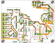
here is an ugly looking draft of B1 with LM317 supply.
what i would like understand is if it would be a good thing to connect signal ground trace only at the LM317's o/p cap (C6). The diode gnd also connects at the same place.
In the attachment all light colored traces (pink/yellow with highlighted pads) represent the gnd signal.
I want to put together an integrated amp using B1 as buffer and JLH 2003. the jlh2003 posted elsewhere, has an option of ground lift resistor.
Would B1 also need a ground lift?
regards
Prasi
Attachments
What is the actual current draw of the Buffer .
its abt 20mA as given by Mr. Pass on the website documentation.
Given this circuit has a projected current draw of 200mA max,..............
What is the actual current draw of the Buffer and it's PSU?........................
Is Bruce using up 180mA in the PSU?its abt 20mA .................
I thought I'd read multiple times 200mA. Now I only find a couple instances and one was corrected to 20mA. All the other sources show the B1 as 20mA max. Thanks for catching that.Is Bruce using up 180mA in the PSU?
Sent from my GT-I9505 using Tapatalk
here is an ugly looking draft of B1 with LM317 supply.
what i would like understand is if it would be a good thing to connect signal ground trace only at the LM317's o/p cap (C6). The diode gnd also connects at the same place.
In the attachment all light colored traces (pink/yellow with highlighted pads) represent the gnd signal.
I want to put together an integrated amp using B1 as buffer and JLH 2003. the jlh2003 posted elsewhere, has an option of ground lift resistor.
Would B1 also need a ground lift?
regards
Prasi
any comments please?
to give more details on what I plan,
The build will have 1 big trafo and 2 CRC PSU for the JLH2003. Dual secondary 24VAC for the JLH amp. separate 18 VAC secondaries for the LM317 and buffer.
Last edited:
Given this circuit has a projected current draw of 200mA max, as I recall, how much over spec'ing are you talking about? I was thinking of a 20VA transformer which should provide 800mA.
At least a1 amp rating.
??At least a1 amp rating.
Did you read 4297 & 4298 and still say this?
20mA in ckt +some loss in PSU,... 500mA trafo are very cheap and common in India. would that be sufficient?
??
Did you read 4297 & 4298 and still say this?
Sent from my GT-I9505 using Tapatalk
Yes, because a larger VA has a natural regulation.
The other way is fine too. If you feel better using just enough that's ok.
Fair enough. Thanks for the clarification.Yes, because a larger VA has a natural regulation.
The other way is fine too. If you feel better using just enough that's ok.
Sent from my GT-I9505 using Tapatalk
I have a B1, no amp as yet, I'm considering either of these two to build, hackernap or twisted pear's sympatico, right now I'm leaning towards the sympatico, which requires a balanced input, which the B1 doesn't have.
How would the following solution work out? It'll add a little gain as far as I can tell, Assembled DRV134PA dual-channel single-ended balance board | eBay
Please advise
How would the following solution work out? It'll add a little gain as far as I can tell, Assembled DRV134PA dual-channel single-ended balance board | eBay
Please advise
Two batteries, switch and cheap Meanwell external charger?
JP
I agree, mines work like a charm...dead quiet...
Sent from my iPhone using Tapatalk Pro
I have a B1, no amp as yet, I'm considering either of these two to build, hackernap or twisted pear's sympatico, right now I'm leaning towards the sympatico, which requires a balanced input, which the B1 doesn't have.
How would the following solution work out? It'll add a little gain as far as I can tell, Assembled DRV134PA dual-channel single-ended balance board | eBay
Please advise
This will work...
But you'll kill the advantage of the simplicity of the B1, which has only one semiconductor in the signal path (that explains the great sound).
I'm in the same situation with my B1 (using a Hypex Ncore amp), and I use a Lundahl LL1527 to symmetries the signal, works fine and sounds great.
I have a B1, no amp as yet, I'm considering either of these two to build, hackernap or twisted pear's sympatico, right now I'm leaning towards the sympatico, which requires a balanced input, which the B1 doesn't have.
Please advise
You could build an F6 pass amp which has an inbuilt buffer.
Balanced is for Bragging rights Or heavy RF studio uses.
Otherwise it will give little if any in your home advantage.
This will work...
But you'll kill the advantage of the simplicity of the B1, which has only one semiconductor in the signal path (that explains the great sound).
I'm in the same situation with my B1 (using a Hypex Ncore amp), and I use a Lundahl LL1527 to symmetries the signal, works fine and sounds great.
You could build an F6 pass amp which has an inbuilt buffer.
Balanced is for Bragging rights Or heavy RF studio uses.
Otherwise it will give little if any in your home advantage.
Well I have decided to go with my original plan of building the HackerNap, I should work great with the B1, though I'm also eyeing these ready made modules HYPA 17 they look pretty good, I had also considered the F5 turbo V3, though I live in the tropics and really don't need a heater.
- Home
- Amplifiers
- Pass Labs
- B1 Buffer Preamp