Hello Juma.I built Jboz with J310. I am using 24V Power supply. one channel draws 10mA with 16.34V at the drain and the other 9.5mA with 16.76V at the drain.Are the drain voltages correct or should they be half the supply voltage ?
I also found a small series shunt PSU you posted on an other forum.Is there a any updated version of it or is it final?I would like to build it.
I also found a small series shunt PSU you posted on an other forum.Is there a any updated version of it or is it final?I would like to build it.
Attachments
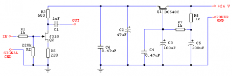
12-14V is the target, but J310 have their Idss in wide range so you should use 1k or so for R3. That will give a bit more gain and higher Zout (mainly determined by value of R3) - or you can lower R5 (to increase the Id) but that will increase Pd in J310 (up to 200mW without the heatsink is OK). I would go for Id of about 15mA at Vds of 12V.Hello Juma.I built Jboz with J310. I am using 24V Power supply. one channel draws 10mA with 16.34V at the drain and the other 9.5mA with 16.76V at the drain.Are the drain voltages correct or should they be half the supply voltage ?
Test and find the compromise that suits your JFETs and ears.
If you have DC offset at the input (gate leakage ) lower the R2.
It works all right, just take care that Vout depends on R2/R3 (R10/R12) ratio - see TL431 datasheet.I also found a small series shunt PSU you posted on an other forum.Is there a any updated version of it or is it final?I would like to build it.
A schade feedback will have low input impedance, hence it is best to have a preceding buffer. Cascoding the jfet will give lower distortion and higher output voltage capability and an output transformer will reduce turn on and off thump. Attached sim shows 2.98 ppm THD, 46.1 Vpp Max with Zout < 200 Ω. 
Attachments
R6 / R21 form the Schade Feedback.R6 and R11 form the Schade feedback loop?...
Transformer is my preference, you can go RC but there will be somewhat loud turn on and off thump.
Hi
I have made a JFET boz to drive a sewa v1 amp. I followed the original schematic, using a 2k2 resistor on drain of the jfet and 10 ohm on source.The JFET (2SK170) that i used has an Idss of 8.1 mA.
I supplied it with 16.3V , but the distortion was very high. I measured the voltage on the drain pin of the jfet and it was 3.4V. I replaced the 10 ohm resistor with a 22 ohm one, the distortion was reduced a bit but it is still too much.
Does anyone have any advice on this matter ?
Thanks
further JFET BOZ question
dear all,
i just build a JFET BOZ and connected it directly to input of Hiraga LeMonstre- without pot, for getting about 6-10 db more gain..
but now it has way too much gain.
can it be reduced?
or can i fix it with input voltage devider with two resistors?
what values should these resistors have for geting about 6 db?
thanks a lot
best
Ralf
- Home
- Amplifiers
- Pass Labs
- Jfet BOZ