I start this thread, because the subject of inductor linearity was raised in this discussion:
https://www.diyaudio.com/forums/equ...software-distortion-analyzer-post6199594.html
As I am also interested in the subject, I carried out some tests.
I tested three very different types of materials: a general-purpose manganese ferrite (grade 3H1), a VHF nickel ferrite (grade 4C4), and an iron-powder/polymer composite of unknown origin.
These are relatively old materials, but the data is still indicative, and more modern grades improve on saturation limit, temperature stability, HF behavior, losses -not on linearity-.
In the days of FDM telephony, linearity had some importance, but that's no longer the case.
I made the tests on X22 cores: they are convenient to work with, and I have plenty of them.
As I hate winding works, I used salvaged, already wound coil-formers as test windings.
This means that I didn't have the choice of the number of turns, but it doesn't really matter: the results have to be normalized anyway.
The tests were made for a zero airgap: what interests us is the core non-linearity for a given induction.
In an actual inductor, this non-linearity will become "diluted" by various factors, but by knowing the source value, it is possible to compute the non-linearity for any situation.
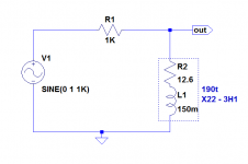
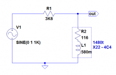
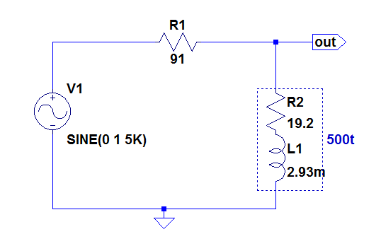
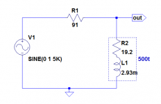
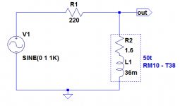
Here is the test-jig for the 3H1:
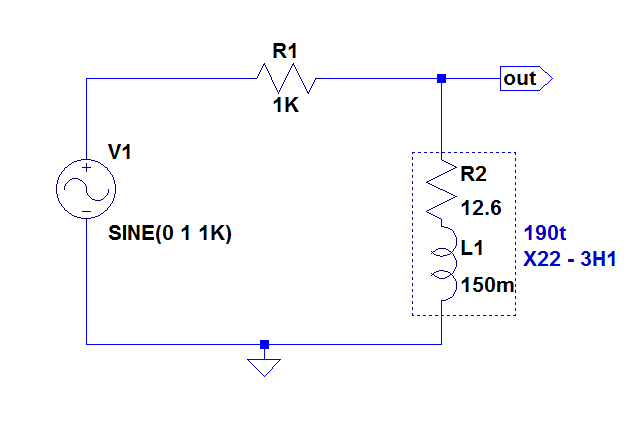
The 1K series resistor is calculated to be ~equal to the reactance of the inductor at the test frequency. It will be the load seen by the harmonics generated by the coil.
The test voltage was varied from 72mV to 2.2Vrms, resulting in a peak induction comprised between 1.293mT and 39.5mT.
Here are the results:
There seems to be a quasi-linear dependency of the non-linearity with the excitation level.
These raw figures will be reduced if an airgap is added.
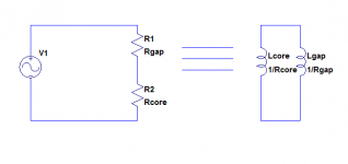
This is the equivalent circuit with an airgap: the reluctances on the left, and the electrical equivalent on the right.
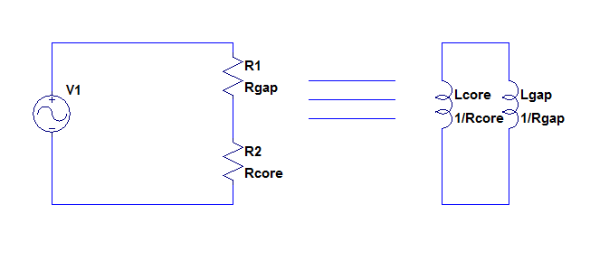
It is obvious that by making Lgap much smaller than Lcore, the THD will be reduced in the same proportion.
Lgap can be computed : n²*µo*Ae/d (Ae= effective area, d= airgap).
The distortion will also be reduced if the excitation level is reduced.
It is counter-intuitive, but adding a gap will not directly reduce the induction: the induction formula does not include any magnetic parameter.
However if the gap is increased, the inductance will decrease and if the excitation voltage and frequency are kept identical, the current will increase, and the greater H will compensate exactly the increased reluctance.
Of course, in general the coil will be adapted to keep the same value with an increased airgap: this means increasing the number of turns by √r, and this will reduce the induction.
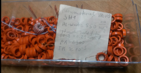
Here is a pic of the cores tested:
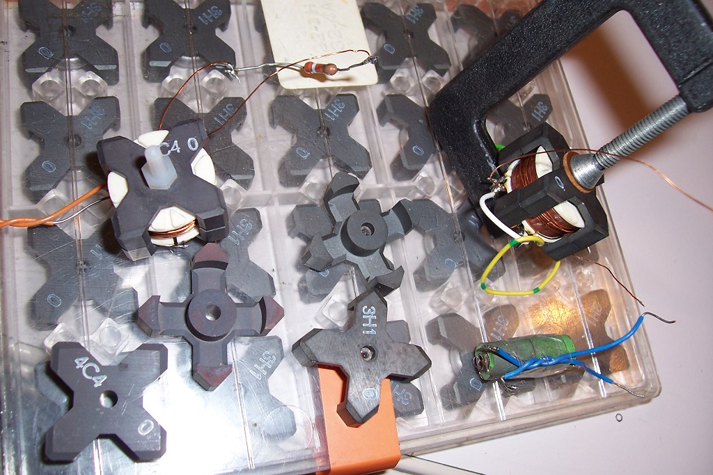
The 4C4 cores are clamped by a nylon bolt, but the 3H1's have a threaded insert and require an external clamp (or the proper mounting hardware).
The iron-powder core is an horrible kludge, more on that later
https://www.diyaudio.com/forums/equ...software-distortion-analyzer-post6199594.html
As I am also interested in the subject, I carried out some tests.
I tested three very different types of materials: a general-purpose manganese ferrite (grade 3H1), a VHF nickel ferrite (grade 4C4), and an iron-powder/polymer composite of unknown origin.
These are relatively old materials, but the data is still indicative, and more modern grades improve on saturation limit, temperature stability, HF behavior, losses -not on linearity-.
In the days of FDM telephony, linearity had some importance, but that's no longer the case.
I made the tests on X22 cores: they are convenient to work with, and I have plenty of them.
As I hate winding works, I used salvaged, already wound coil-formers as test windings.
This means that I didn't have the choice of the number of turns, but it doesn't really matter: the results have to be normalized anyway.
The tests were made for a zero airgap: what interests us is the core non-linearity for a given induction.
In an actual inductor, this non-linearity will become "diluted" by various factors, but by knowing the source value, it is possible to compute the non-linearity for any situation.
Here is the test-jig for the 3H1:
The 1K series resistor is calculated to be ~equal to the reactance of the inductor at the test frequency. It will be the load seen by the harmonics generated by the coil.
The test voltage was varied from 72mV to 2.2Vrms, resulting in a peak induction comprised between 1.293mT and 39.5mT.
Here are the results:
Code:
^B(mT)        k(%)

1.293         0.023
3.95          0.062
12.93         0.175
39.5          0.45
There seems to be a quasi-linear dependency of the non-linearity with the excitation level.
These raw figures will be reduced if an airgap is added.
This is the equivalent circuit with an airgap: the reluctances on the left, and the electrical equivalent on the right.
It is obvious that by making Lgap much smaller than Lcore, the THD will be reduced in the same proportion.
Lgap can be computed : n²*µo*Ae/d (Ae= effective area, d= airgap).
The distortion will also be reduced if the excitation level is reduced.
It is counter-intuitive, but adding a gap will not directly reduce the induction: the induction formula does not include any magnetic parameter.
However if the gap is increased, the inductance will decrease and if the excitation voltage and frequency are kept identical, the current will increase, and the greater H will compensate exactly the increased reluctance.
Of course, in general the coil will be adapted to keep the same value with an increased airgap: this means increasing the number of turns by √r, and this will reduce the induction.
Here is a pic of the cores tested:
The 4C4 cores are clamped by a nylon bolt, but the 3H1's have a threaded insert and require an external clamp (or the proper mounting hardware).
The iron-powder core is an horrible kludge, more on that later
Attachments

Methinks 3H1 is a bad choice. I still have 3H1 ring cores I bought as a student 40 years
ago from someone at the daily mini flea market at the mensa building of the TU Berlin.
They have astronomic Mu-r, but it collapses with the slightest dc current. Barely usable
as a choke between small signal stages.
That must be where the word "lifetime supply" comes from.
ago from someone at the daily mini flea market at the mensa building of the TU Berlin.
They have astronomic Mu-r, but it collapses with the slightest dc current. Barely usable
as a choke between small signal stages.
That must be where the word "lifetime supply" comes from.
Attachments
Last edited:
I did similar tests some time ago to evaluate inductors for class-D output filters. My test setup was comprised of Laptop, USB-soundcard, ARTA, my very low THD lat-FET-amp and a 10R dummy in series with the inductor as the measurement output. So I could compare THD behind and before the inductor as a reference.
Measurements with ungapped cores are prone to high tolerance of u-rel so I prefer measurements with the more realistic gapped cores, pot cores for instance.
Doing so you will find THD increases with frequency as well. For that reason specifying measure frequency is mandatory.
And, of course, the bigger the core, the less magnetic swing and the less THD you will get.
I think the low frequency high flux swing ferrites like N87 are best for these applications.
Last edited:
Ungapped magnetic cores have ~zero tolerance to DC: the slightest DC component is sufficient to cause saturation (except for materials having a distributed airgap, like FPC). That is why toroidal transformers buzz and groan as soon as the mains is unbalanced.Methinks 3H1 is a bad choice. I still have 3H1 ring cores I bought as a student 40 years
ago from someone at the daily mini flea market at the mensa building of the TU Berlin.
They have astronomic Mu-r, but it collapses with the slightest dc current. Barely usable
as a choke between small signal stages.
The reason is easy to understand: the induction formula is B=V/(4.44*F*n*Ae). When F=0 (DC), the induction becomes infinite.
The 3H1 is a completely ordinary material, which is why I used it for the tests.
It has a µr of 2300, which is quite moderate compared to other grades: the 3E7 has 15000, and it is not the highest.
In my test, the maximum peak induction reaches 39.5mT, less than 1/10th of the saturation value
Such a test is valid for a specific application, for a very narrow set of conditions.I did similar tests some time ago to evaluate inductors for class-D output filters. My test setup was comprised of Laptop, USB-soundcard, ARTA, my very low THD lat-FET-amp and a 10R dummy in series with the inductor as the measurement output. So I could compare THD behind and before the inductor as a reference.
It can be useful to evaluate the impact of a component in a particular circuit, but it has no general value
Measurement on the ungapped core gives you access to the source parameter, which allows you to compute the non-linearity for any conditions, and is much more sensitive.Measurements with ungapped cores are prone to high tolerance of u-rel so I prefer measurements with the more realistic gapped cores, pot cores for instance.
Doing so you will find THD increases with frequency as well. For that reason specifying measure frequency is mandatory.
And, of course, the bigger the core, the less magnetic swing and the less THD you will get.
I think the low frequency high flux swing ferrites like N87 are best for these applications.
When the values are normalized for induction, the dependency on frequency and other conditions disappears.
The basic B/H non-linearity remains constant for a very wide range of frequencies. At very high frequencies (hundreds of kHz for the 3H1), other phenomenons begin to appear, but that is well beyond the normal range of frequencies for this material.
Magnetic concepts aren't particularly easy or intuitive, which is why I took care to explain the methods and formalism.
Here is the test jig for the 4C4 (NiZn) ferrite:
The test voltage ranged from 0.25V to 8Vrms.
Code:
^B(mT)       k(%)

0.56         0.022
1.84         0.085
5.6          0.195
18.4         0.63
Despite the hugely dissimilar materials, the general behavior remains broadly the same, but for a given induction the distortion is higher.
The test was also done at 1kHz
Attachments
I guess you are right with comparing ungapped cores. The main reason I do not like ungapped measurements is the problem to guarantee a zero gap with real core halves. For that reason factory measurements are performed with toroids. Maybe this can be compensated by measuring the resulting u-rel and adding it to the calculations.
Following your explanations in my measurement setup THD should be invariant vs frequency at constant current flow - which is not the case. Do you have some explanation for that phenomen?
Following your explanations in my measurement setup THD should be invariant vs frequency at constant current flow - which is not the case. Do you have some explanation for that phenomen?
Last edited:
Yes, the ideal shape for material measurement is a toroid: it has a guaranteed zero gap, there are no section inhomogeneities, and the shape is canonical: the field lines would follow the core shape even when µr is 1.I guess you are right with comparing ungapped cores. The main reason I do not like ungapped measurements is the problem to guarantee a zero gap with real core halves.
I do not have the means of making custom toroids, and the goal of the exercise is to evaluate the feasibility of ultra-low distortion inductors for Edmond (and for me).
Even if the result is 25% off, it does not matter too much: questions are, is it practicable, and in what conditions?
There is no real substitute to a real zero-gap. One could add known, very accurate airgaps to get back to raw permeability, but that would add many sources for errors.For that reason factory measurements are performed with toroids. Maybe this can be compensated by measuring the resulting u-rel and adding it to the calculations.
Yes, the THD of the voltage across the inductor should be invariant, but the proportion between that voltage and the voltage across the load will vary with frequency (if I understood your setup correctly).Following your explanations in my measurement setup THD should be invariant vs frequency at constant current flow - which is not the case. Do you have some explanation for that phenomen?
In addition, the repartition of the harmonic voltages will obey the usual Kirchoff's laws, and I am not completely certain about the internal impedance of the inductor under test as generator.
This would need to be clarified, but in the meantime I made sure to make the load impedance equal to the reactance of the inductor as a tradeoff and possibly worst-case
This is the test jig for the iron powder/polymer composite:
As I warned in the first post, this one is a messy kludge: I know I have potcore sets made of FePC somewhere, but I haven't seen them in 20 years, and I don't want to waste a day or two scouring my attic.
As a result, I had to use something vaguely resembling a closed magnetic assembly: I used an adjustment screw as a core, and I wound 500t of enamelled wire.
I then inserted the wound screw into a coil cover (~bell shaped). As this left one side open, I inserted another bell to close the magnetic circuit.
The result in not tidy: the core area is not homogeneous, and there are three parasitic airgaps.
In addition, I had to make the measurement at 5kHz, because of the low inductance value.
This means that contrary to the two previous ones, this set of measurements is purely indicative.
Up to 6mT, the THD remains quite low, but it increases very quickly afterwards.
Because of the parasitic gaps, the values are optimistic and should be corrected.
If the gaps are 0.3mm each, the total is 0.9mm. With an estimated core area of 14mm², the gap inductance is 5.58mH. This means that the core's inductance without gaps should be 6.19mH.
To take into account the dilution factor, the THD figures should be increased by 6.19/2.93=2.11.
These are very crude estimations, of course.
Even after correction, the figures still look attractive, but of course the relative permeability of these cores is very low, and they require a lot of turns to achieve a given inductance.
As I warned in the first post, this one is a messy kludge: I know I have potcore sets made of FePC somewhere, but I haven't seen them in 20 years, and I don't want to waste a day or two scouring my attic.
As a result, I had to use something vaguely resembling a closed magnetic assembly: I used an adjustment screw as a core, and I wound 500t of enamelled wire.
I then inserted the wound screw into a coil cover (~bell shaped). As this left one side open, I inserted another bell to close the magnetic circuit.
The result in not tidy: the core area is not homogeneous, and there are three parasitic airgaps.
In addition, I had to make the measurement at 5kHz, because of the low inductance value.
This means that contrary to the two previous ones, this set of measurements is purely indicative.
Code:
^B(mT)        k(%)
0.608         0.0037
1.92          0.0058
6.08          0.016
19.2 0.38Because of the parasitic gaps, the values are optimistic and should be corrected.
If the gaps are 0.3mm each, the total is 0.9mm. With an estimated core area of 14mm², the gap inductance is 5.58mH. This means that the core's inductance without gaps should be 6.19mH.
To take into account the dilution factor, the THD figures should be increased by 6.19/2.93=2.11.
These are very crude estimations, of course.
Even after correction, the figures still look attractive, but of course the relative permeability of these cores is very low, and they require a lot of turns to achieve a given inductance.
Attachments
Correction: re-reading the results, I found the last line suspicious: the huge jump in THD for just a 10dB increase can only happen at some boundary, like saturation or coercivity, unlikely here which is why I did the measurement again and in fact the actual value is 10 times lower.
Maybe I missed a decimal place or the setup had a bad contact, I don't know, but here is the corrected table:
These results should also be corrected by the ~2 (?) factor, and taken with some caution and a pinch of salt.
However, they indicate that iron dust is no miracle material...
Maybe I missed a decimal place or the setup had a bad contact, I don't know, but here is the corrected table:
Code:
^B(mT)        k(%)
0.608         0.0037
1.92          0.0058
6.08          0.016
19.2          0.038
These results should also be corrected by the ~2 (?) factor, and taken with some caution and a pinch of salt.
However, they indicate that iron dust is no miracle material...
Very approximately, yesSo, an order to B worsens about an order to THD (+-).
Also true: the relationship is non-linear, and depends on the material. It is a fractional exponent comprised between 0.5 (square root) and 1 (straight linear dependency). A value of 2/3 seems the best fit for this range of induction: low or very low level.No. Elvee's table says there's a non-linear relationship between B and THD.
Best regards!
For other ranges (close to saturation f.e.), it is certainly widely different (much steeper).
Here, we are looking at signal-level inductors, for filters, etc. For power applications, the situation is certainly different.
I am in the process of testing other materials, to confirm (or infirm?) the general tendency
PS:
There are certainly academic papers treating the subject, but I took care not to make any searches before making my own tests and opinion: I want to be sure to start afresh.
If my findings diverge from the mainstream corpus of knowledge, it will be interesting to find why
Last edited:
I have tested two other materials, from Siemens/Epcos this time.
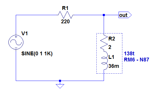
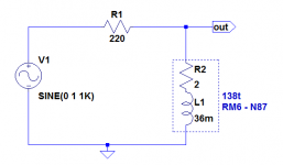
A RM6 core, N87 material. Test jig:
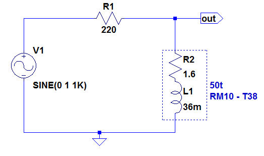
A RM10 core, T38 material. Test jig:
The distortions are higher than for the previous cases, but the induction level is also higher (due to the pre-wound coil-formers I was able to find).
The N87 grade is significantly worse though, which is logical since this material is intended for power applications.
I also made another test, to evaluate the internal impedance of the non-linearity source in the inductor: I replaced the 220 ohm series with a 470 ohm one (and I readjusted the injection level to arrive at the same induction).
The results are interesting, and confirmed my initial guess:
The increase with the load impedance means that the equivalent generator impedance is the inductance.
This probably doesn't hold at very high levels, but for low-dist applications, that's all you need to know
A RM6 core, N87 material. Test jig:
Code:
^B(mT)      k(%)

3.8         0.26
12.1        0.54
38          1.4
121         2.8
A RM10 core, T38 material. Test jig:
Code:
^B(mT)     k(%)

6         0.18
19        0.45
60        1.15
190       5.2
The distortions are higher than for the previous cases, but the induction level is also higher (due to the pre-wound coil-formers I was able to find).
The N87 grade is significantly worse though, which is logical since this material is intended for power applications.
I also made another test, to evaluate the internal impedance of the non-linearity source in the inductor: I replaced the 220 ohm series with a 470 ohm one (and I readjusted the injection level to arrive at the same induction).
The results are interesting, and confirmed my initial guess:
Code:
^B(mT)     k(%)

6         0.29
19        0.69
60        1.8
190 8.5This probably doesn't hold at very high levels, but for low-dist applications, that's all you need to know
Attachments
Last edited:
This study is far from exhaustive, but I think we have enough elements to draw conclusions and provide guidelines.
Some are pretty obvious, and confirm the general knowledge about the subject:
-Use a gap as large as possible: it has two beneficial effects: it "dilutes" the non-linear µr of the magnetic material into the (quasi) linear µo of the vacuum (µo is probably slightly non-linear too, otherwise our universe would fall apart, but this can be safely neglected).
It also reduces the peak induction seen by the core, because adding an airgap mandates an increase in the number of turns to keep the same inductance, and a larger number of turns reduces the induction if the frequency and voltage are kept constant.
There is of course a limit to the possible increase in the number of turns: for a given core size, the winding window is limited, and more turns means finer wire, thus increased losses.
How much copper losses can be tolerated? it very much depends on the exact application.
The induction-reduction effect on THD will be relatively weak: because the number of turns will increase as the square-root of the gap increase, and the THD to B dependency isn't linear either: the exponent is somewhat smaller than 1 (for low inductions anyway).
By contrast, the dilution effect of the gap is linear, and is not practically limited: with the induction, once you have reached the acceptable copper loss limit, that's it: you hit a wall.
The dilution effect is limited only by the µr of the material, and you will not need to adjust the gap to take the µr into account, because for ferrites, µr is so much larger than 1, having a µr of 2300 as for the 3H1 example, or 23000 for a hypothetical material, that only the gap will determine the µapparent, thus the inductance. This means that you can change the core material completely, as long as you keep the same shape, gapped in the same way.
The apparent permeability change will be negligible, but the linearity will be greatly impacted.
The permeability of ferrites does not seem to impact their linearity, so the choice of a very high-perm material looks like the best choice.
The T38 I tested is a possibility, but the 3E9 from Philips/ferroxcube looks even more promising, with a µr of 20000.
https://ferroxcube.home.pl/prod/assets/sfmatgra_frnt.pdf
If you reduce the µapparent of such an ungapped core from 20000 to 200 (which is still substantial), you will reduce the intrinsic THD by a factor 100.
There are variations among materials, and the ferroxcubes seems to be more linear than the Epcos varieties (which doesn't mean that they are worse: low-level linearity is specified nowhere, and the difference probably results from different optimization tradeoffs).
Modern ferrites are used almost exclusively for power and pulse applications, and the low-level characteristics have to be measured by the user.
Materials specifically designed for power (high Bsat) look significantly worse though.
There are many other manufacturers of ferrites, and some may be marginally better than others, but basically, all MnZN materials have the same overall behavior.
NiZn materials (high-frequency) are somewhat worse, and have a much lower µr, so they are not recommended.
Iron powder in an organic binder looks better, but the permeability is ridiculously low, and the choice of shapes is extremely limited.
I didn't test metal powder toroidal cores, but they have a higher µ, are not adjustable, and difficult to wind for very large number of turns.
Another way to improve the linearity is to opt for a larger core: the effective area will be larger, the copper window too, thus it will automatically improve matters.
The topology of the circuit can also have an impact: because the non-linearities source has an internal impedance ~=the inductance, it might be possible to redraw some circuits to take advantage of this fact.
When possible, the circuit should be arranged to minimize the voltage across the inductance, especially at low frequencies, as it will reduce the induction.
Finally, a word about the gapping method: for DIY, it is tempting to simply use spacers, but this is far from ideal.
It is known that if the gap is located elsewhere than under the source of the magnetomotive force (winding), it results in a ill-defined inductance and high dispersion fields.
Here, it would also cause a sensitivity to external stray fields, because the magnetic shielding will have a void, so gapping the central pillar or leg alone is essential.
A possibility to reduce the sensitivity to external fields whilst reducing the induction is to split the inductance in two series coils wired in opposition.
Is all of that going to make possible a very low dist inductor down to 20Hz?
Difficult to answer the question without knowing all the quantitative specifics of the problem.
Last edited:
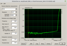
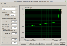
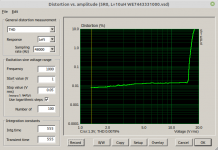
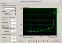
Exploring core distortion I measured THD along 5R0 dummy with various inductors connected in series. In my stash are several standard inductors and some special class -d-inductors. Inductance was 10uH or similar, current amplitude at clipping about 4 amps.It can be seen that specific class-d inductors generate about one order of magnitude less distortion than the standard coils. This is not a matter of the brand, my samples from Coilcraft, Ferrocore and Codaca showed similar results. Obviously there exists some extra linear ferrite composition. Worst linearity was observed with carbonyl (iron powder) inductors.
I append some plots
Attachments
-
 THD_1kHz_5R0_10uH_CC_15x15x9mm.png43.8 KB · Views: 160
 -
 THD_1kHz_5R0_8uH2_Codaca_13x11x11mm.png44.6 KB · Views: 92
 -
 THD_1kHz_5R0_10uH_CC_GA3416_CL.png45.2 KB · Views: 92
 -
 THD_1kHz_5R0_10uH_Ferrocore_SHI-215145MZ.png45.2 KB · Views: 88
 -
 THD_1kHz_5R0_10uH_WE74435561100.png44.1 KB · Views: 94
 -
 THD_1kHz_5R0_10uH_WE_7443331000.png43.9 KB · Views: 81
 -
 THD_1kHz_5R0_L_0.png43.3 KB · Views: 86
The reactance of a 10µH @1kHz is a minuscule 62 milliohm, about 1/100th of the load impedance.
This means that the actual inductor's distortion is 100x larger than what you measure.
The coil construction probably matters more than the material in itself: the worst WE one is shielded, meaning a closed (and gapped) magnetic circuit.
I expect more open designs to perform better, but other factors play a role
Yes, I am aware of that. But the minuscule non-linear reactance contribution can be measured in my setup as well. And the question was difference in linearity, i.e. a relative comparision of cores, not absolute values. Just showing big variations of core linearity.The reactance of a 10µH @1kHz is a minuscule 62 milliohm, about 1/100th of the load impedance.play a role
As a side effect I discovered remanence effects while sweeping up the level with steps. Better reproduction was observed with starting at max level sweeping down - similar to de-gaussing the CRT
Yes, magnetic materials are curious beasts. In addition, in a class D amplifier, the high level of HF superimposed on the signal probably contributes heavily to the reduction of hysteresis distortion in the material, just like for magnetic recording.
If you want to measure more accurately and more easily the THD of the coil alone, adopt my test configuration: L and R swapped.
This will give you a much finer resolution.
If you want to measure more accurately and more easily the THD of the coil alone, adopt my test configuration: L and R swapped.
This will give you a much finer resolution.

- Home
- Design & Build
- Parts
- Non-linearities of cored inductors