Yes, and there is also an important dfference: your focus is on high, near-sat levels, whereas my tests evaluate the signal-level behavior; OK, I ventured up to 190mT in one of the tests, but for bandpass, notch or LP filters used at line level, the mT range is more relevant, and that was what I mainly tested.
At these low levels, only the residual hysteresis of µi is really important.
At your levels, you first pass the amplitude permeability threshold, then reach saturation.
A material can have good saturation properties (like the N87), and have a poor initial hysteresis.
By contrast, I am pretty sure that the 3E9 material I proposed (µ=20000) has a very early and very hard saturation behavior.
I have no sample to test and confirm, but in engineering you can rarely have your cake and eat it
Agreed. Our common problem is that no manufacturer data are available in this field, so all is trial and error. I could send you one of my bigger ferrocore inductors if that helps. These are bobbin-less pot cores with glued halves, quite similar to WE 7443630700. Applying some heat will open them. This range of inductors has constant Rdc over various inductances, i.e. same winding construction and different gaps.
Last edited:
Thanks, but I don't think it is worth the trouble (unless Edmond or others want to investigate this material in greater details).I could send you one of my bigger ferrocore inductors if that helps.
In the meantime, I have tested the effect of HF bias on the low-level linearity of ungapped inductors.
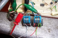
I have used CMC's, because they are pre-wound and have a solid, gapless core.
They are Siemens 2 x 27mH, and I have added 31 turns to inject the HF bias.
The 4 27mH are wired in series, resulting in ~216mH total inductance.
The 31t windings are wired in opposition, and are therefore not coupled, except parametrically, through the material properties (and also marginally through parasitic capacitances).
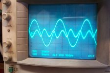
A 500Hz signal is injected, resulting in a ~0.6% THD, with no HF bias.
This pic shows the signal and the THD residual:
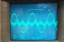
When the 50KHz is applied, the THD first decreases to ~0.4%, but then increases again on the THD-meter when the level is increased further, because the 50kHz leaks into the output (inductors are not matched or balanced), and corrupts the THD value.
However, it can be seen that the LF envelope of the HF hash has decreased to ~half of its initial value:
The amplitude of the 500Hz has also very slightly increased, meaning that more energy concentrates on the fundamental.
The improvement is not huge (~6dB), but it is significant, and it is just a quick and dirty test, improvised with what's available.
The method could probably refined
Attachments

The pilot tone spreads out the input excitation across a window of the BL curve, where the effective BL value becomes the integral of the BL across the window as the signal shifts the window across the BL curve. The reduction in distortion is then dependent on the size of the window and how much of the BL curve it can integrate.
To increase the window you can halve the frequency of your pilot tone to double the current, then maybe you would get another 6db reduction. Or you could double the voltage of the pilot tone. Or reduce the number of turns of the pilot tone windings.
To increase the window you can halve the frequency of your pilot tone to double the current, then maybe you would get another 6db reduction. Or you could double the voltage of the pilot tone. Or reduce the number of turns of the pilot tone windings.
Thinking about it more, the more you increase the pilot tone, the more you reduce the effective inductance as you average out the peak at zero magnetzation. It may be that you didn't increase the magnitude of the signal tone by adding the pilot, rather you reduced the compression at peaks. But it's hard to imagine how 0.3% would be visible on an oscilloscope. The difference in peak on that scope is more like 5%.
The waveform of the pilot tone makes the averaging occur over a weighted window. A sine wave spends more time near it's peaks, so the middle region could be said to be skipped over. A square wave would be the maximization of this effect. A triangle wave would give a rectangular window with no weighting.
You would want to weight the pilot waveform toward the areas of the BL curve with the least curve. So does it curve more in the middle or on the sides? Not much difference?
Your pilot tone is at 50KHz and your signal tone is at 500Hz but your pilot voltage is about 1/10 of your signal voltage. So the magnetization of your pilot tone is something like 1/1000 that of your signal tone. Since that is that case I'm surprised you got any distortion reduction at all. Magnetization depends on current, so your pilot tone should have something like 1/10 the current of your signal tone, adjusted for turns ratio of course.
Also it may be worth thinking about whether you are using current or voltage drive for the pilot tone. If you use voltage drive then the core gets pushed further into magnetization when the drop in inductance allows more current through. This worsens the drop in BL which increases distortion, so what we actually want is current drive for the pilot tone. Modulation should be visible on the pilot tone voltage.
Here's an idea. Put oppositely DC biased inductors in series. This way you shift the BL curves to the side and two humps becomes a single, wider hump, maybe even with a nice flat plateau in the middle. Sort of like XBL^2 motors in speakers. I think this might actually be equivalent to the square wave pilot tone, but perhaps much less complex.
The HF bias is 25Vpp, against 1Vpp for the signal.
The Oscope screen shows the fundamental and the residue from the THD analyser.
The inductors are arranged in a "transducer" configuration, there is no direct coupling between them.
The THD reduction can be explained in the frequency domain by examining the multiple IM products between the bias and the signal's harmonics, and the way they cancel each other and the signal's harmonics, whilst reinforcing (very slightly) the fundamental
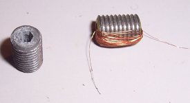
I have measured another iron/polymer core, a screw adjuster for VHF coils.
The shape lends itself to the measurements: it has an hexagonal hole for its whole length, meaning it is like an elongated toroid, without airgap.
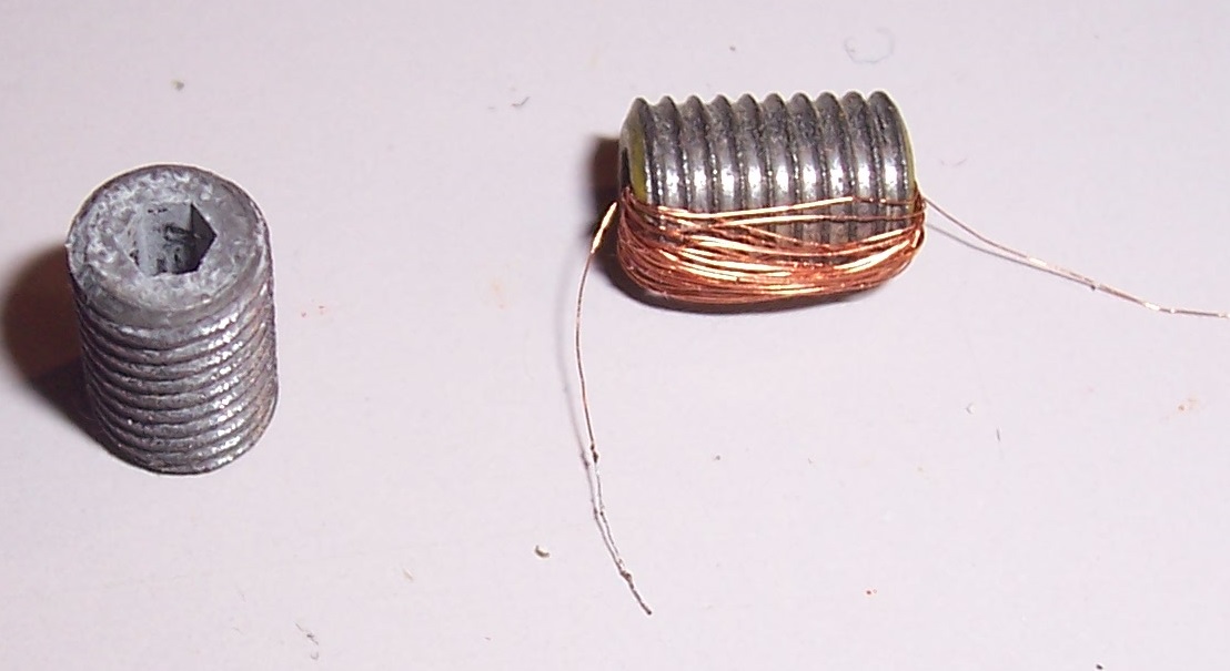
I made the measurement at 10kHz, because with the 40 turns of the test winding I only managed 66.5µH.
The effective area is something like 16mm², not very accurate due to the shape of the internal hole.
With an Î of 7.45mA, the peak induction reaches 0.774mT.
Under those conditions, the distortion corrected for the winding's resistance is 0.14%, which is rather substantial considering the small excitation level.
It is possible to estimate the impact when used as intended, inside a cylindrical coil.
From the measured parameters, the relative permeability of the material, µr is ~9, which is normal for a VHF material.
When the screw is fully inserted in the coil, it ~doubles its value.
The reluctance of the circuit is thus halved, and due to the permeabilty, the core intercepts ~1/10th of the magnetomotive force.
Put together, these effects lead to distortion dilution of ~1/20, or 0.007% for the complete inductor, which is surprisingly large.
Morality: using low µ, VHF materials for AF applications is counterproductive.
At the same induction, the AF ferrite material 3H1 has 1/10th of the distortion, and the HF one, 4C4 one-fifth.
But these materials have a much higher permeability than 9, meaning they see a much smaller fraction of the total magnetomotive force, leading to a much higher dilution ratio, to the tune of several thousands.
As I have a real application in mind, I will try to find compatible adjusters made of ferrite. Even the worst possible ferrite will be much better than these iron cores
The shape lends itself to the measurements: it has an hexagonal hole for its whole length, meaning it is like an elongated toroid, without airgap.
I made the measurement at 10kHz, because with the 40 turns of the test winding I only managed 66.5µH.
The effective area is something like 16mm², not very accurate due to the shape of the internal hole.
With an Î of 7.45mA, the peak induction reaches 0.774mT.
Under those conditions, the distortion corrected for the winding's resistance is 0.14%, which is rather substantial considering the small excitation level.
It is possible to estimate the impact when used as intended, inside a cylindrical coil.
From the measured parameters, the relative permeability of the material, µr is ~9, which is normal for a VHF material.
When the screw is fully inserted in the coil, it ~doubles its value.
The reluctance of the circuit is thus halved, and due to the permeabilty, the core intercepts ~1/10th of the magnetomotive force.
Put together, these effects lead to distortion dilution of ~1/20, or 0.007% for the complete inductor, which is surprisingly large.
Morality: using low µ, VHF materials for AF applications is counterproductive.
At the same induction, the AF ferrite material 3H1 has 1/10th of the distortion, and the HF one, 4C4 one-fifth.
But these materials have a much higher permeability than 9, meaning they see a much smaller fraction of the total magnetomotive force, leading to a much higher dilution ratio, to the tune of several thousands.
As I have a real application in mind, I will try to find compatible adjusters made of ferrite. Even the worst possible ferrite will be much better than these iron cores
Attachments
- Home
- Design & Build
- Parts
- Non-linearities of cored inductors