I designed a speaker protection dc detect circuit with a micro and a relay.
I would have thought the relay coil would only work in one polarity as each polarity will swing the magnetic field one way or the other.
My relay doesn't crae about coil polarity, it works bot hways.
Some relays do have + and - marking on the coils but a lot don't.
Does anyone know the reason why ?
I would have thought the relay coil would only work in one polarity as each polarity will swing the magnetic field one way or the other.
My relay doesn't crae about coil polarity, it works bot hways.
Some relays do have + and - marking on the coils but a lot don't.
Does anyone know the reason why ?
Some relays do have + and - marking on the coils but a lot don't.
Polarized relays use a permanent magnet.
There are a few major variations on relays. Not exhaustively including:
- Simple solenoid
- latching
Latching relays tend to be polarity sensitive, and have rather specific drive requirements. You will know if you bump into one of these. As noted by the previous post, these are a real thing.
The vast majority of relays are pretty much boring old solenoids. You will see AC and DC variants. This is largely a function of the coil design to achieve adequate pull in force on the solenoid.
DC relays are still just solenoids, but the inductance is largely irrelevant in terms of current draw which differentiates their design from AC relays.
Yes, polarity in a DC relay will determine the magnetic field direction - but remember the solenoid / magnet is acting on a lump of iron. Not usually a magnet. So in general polarity is irrelevant.
EXCEPT... There are a reasonable number of relays out there that include a built in you back diode. Remember that whole a DC current is not affected by the inductance of the relay coil, when you turn the relay off it is no longer a DC current! The discontinuity in current delivered by the relay drive results in a back EMF from the coil fully capable of killing a lot of driver circuits. Many Omron relays for example have a diode across the coil to catch this.
This makes there relays polarised.
I have got a hypo sensitive relay in a box deep down in my archive.
From my 1970s memory of opening it up to see what was inside there is a meter movement coil and a tiny single pole changeover switch.
It is obviously polarity sensitive and switched if connected in series with an ORP12 and a voltage I can't remember now.
From my 1970s memory of opening it up to see what was inside there is a meter movement coil and a tiny single pole changeover switch.
It is obviously polarity sensitive and switched if connected in series with an ORP12 and a voltage I can't remember now.
Also somewhat common in miniature telecom relays, one of the more annoying layout stuffups is getting the coil backwards (BTDT).If you look at the low current / high resistance relays, they will be of this construction.
Incidentally a lovely one that caught our production department was testing a box containing relays while resting it on top of a 1U box containing a loudspeaker.... Caused us fits trying to figure out why the relays were sticking in test but not on my bench!
Regards, Dan.
High power relays and contactors use permanent magnets (one each end of the armature) to make them faster acting thus reducing arcing time. 30 years ago, contactors with DC coils always had lower current ratings than their AC counterparts, but not any more. With AC coils, when the magnetic circuit is open, the coil current is high so the contactor will move quickly, but the open magnetic circuit doesn't cause a high current with DC coils as the final current is limited by the DC resistance only
Brian
Brian
There are bistable relays.which may have two coils marked Set/Reset or or one CT coil.I designed a speaker protection dc detect circuit with a micro and a relay.
I would have thought the relay coil would only work in one polarity as each polarity will swing the magnetic field one way or the other.
My relay doesn't crae about coil polarity, it works bot hways.
Some relays do have + and - marking on the coils but a lot don't.
Does anyone know the reason why ?
Relays also come equipped with back EMF clamping diode which is of course polarity conscious.
Dan.
...I would have thought the relay coil would only work in one polarity as each polarity will swing the magnetic field one way or the other.....
Take a permanent magnet. Put the N pole to a pin. It attracts. Put the S pole to a pin. It attracts. The basic relay is polarity agnostic.
Same for an electromagnet. Flip the wires. It still attracts a pin.
As said, some do have a small permanent magnet to reduce current needed.
Relays switched by transistors/CPUs "need" a reverse diode to catch the kick-back when current stops. The system designer is expected to put one in. But as a convenience, some mini-relays have that diode built-in, and thus have a polarity.
There are relays with an LED, very convenient for diagnosis in large systems. While the ones in my furnace are AC, if a DC relay has an LED it either has a polarity or some way to light the LED either way (could be a simple dual-die LED).
Incidentally, a diode shunt does cause a de-energise delay. Whether this is important depends on the application. In power switching it might shorten the life of the contacts.
The simplest way to avoid this problem is to use a suitable zener in series with the diode.
The details can be found here:
https://www.te.com/commerce/DocumentDelivery/DDEController?Action=srchrtrv&DocNm=13C3264_AppNote&DocType=CS&DocLang=EN
The simplest way to avoid this problem is to use a suitable zener in series with the diode.
The details can be found here:
https://www.te.com/commerce/DocumentDelivery/DDEController?Action=srchrtrv&DocNm=13C3264_AppNote&DocType=CS&DocLang=EN
It might be even simpler to specify a 300V transistor; this approach requires zero extra components.Incidentally, a diode shunt does cause a de-energise delay. ... The simplest way to avoid this problem is to use a suitable zener in series with the diode. ...
A normal 1N4148 diode in series with a zener diode requires two extra components.
A zener diode to ground requires only one extra component. If the transistor's Absolute Maximum Rating for collector-to-emitter voltage is "V" volts, select a Zener voltage which is less than 80% of V volts. For example if the transistor is a BD139 rated for 80 volts, choose a 1N5264B zener diode rated for 60V ±5%.
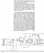
This topic is covered in Douglas Self's book Audio Power Amplifier Design, 6th edition, excerpt below
_
Attachments
")
It might be even simpler to specify a 300V transistor; this approach requires zero extra components.
A normal 1N4148 diode in series with a zener diode requires two extra components.
_
I have designed a few model train electronic controllers.
I had noticed the relay is quieter when it drops out compared to when it turns on. I have updated my next version pcb's to use a 1n4004 and a 12 volt Zener.
That should help the relays last a bit longer.
You don't need a zener, just a resistor in series with the diode will work too.Incidentally, a diode shunt does cause a de-energise delay. Whether this is important depends on the application. In power switching it might shorten the life of the contacts.
The simplest way to avoid this problem is to use a suitable zener in series with the diode.
Using a 300V transistor switching a relay coil without a clamp sounds like a lousy way to select transistors for avalanche capability, something one might be able to get away with occasionally on a hobby basis, but not in a production environment. Dropping an oscilloscope probe across the transistor during the switching event might be eye-opening indeed.
The diode plus resistor approach sounds cost-effective - you do need some extra back emf to make the field collapse quicker in the relay coil and make the contacts let go in a timely manner.
If you don't care about some extra current though the transistor while the relay is on, it seems like you could get away with just a simple shunt resistor across the relay coil. At the cost of a somewhat higher voltage rating on the switching transistor, you could make the shunt resistor a significant multiple of the relay coil resistance .
The diode is the usual well proven way to protect the transistor.
What is the delay value because of the diode ?
I do not see why it has some damaging effect on the relay contacts. Is this known and proven ?
Should I believe an application note with only talks and no MTBF study ?
The free wheeling diode is the safe way when switching inductive loads, uncontrolled over voltages stress the relay coil too, and the PCB.
Last edited:
- Status
- This old topic is closed. If you want to reopen this topic, contact a moderator using the "Report Post" button.
- Home
- Design & Build
- Parts
- Relay coils polarity, why some matter and others dont ?