Classic relay data and handbooks of the 1940s had NO mention of flyback diodes, even on 130V relays.
Telephone systems were millions of relays without diodes.
Remember that insulation was not so good then.
While I see the point about spikes and end-effects, it does not seem to be A Problem.
Telephone systems were millions of relays without diodes.
Remember that insulation was not so good then.
While I see the point about spikes and end-effects, it does not seem to be A Problem.
Classic relay data and handbooks of the 1940s had NO mention of flyback diodes, even on 130V relays.
Telephone systems were millions of relays without diodes.
Remember that insulation was not so good then.
While I see the point about spikes and end-effects, it does not seem to be A Problem.
1940 Relays were not driven by transistors, not invented yet.
Millions yes, during the age of switching circuits telephony that ended in the 80s. With diodes when transistor driven.
Telephony exchanges were running on 48 V DC.
Last edited:
> 1940 Relays were not driven by transistors, not invented yet.
> Telephony exchanges were running on 48 V DC.
Obviously.
I apologize for not citing the context.
The context is zigzagflux's question or assertion that the turn-off spike on a relay may break-down coil insulation. Mark's excellent experiment shows a 12V relay may throw 600V spike, so there's meat in the question.
While I see the issue, it does not appear to come-up in any of the relay application materials written before the age of transistors or (cheap) diodes. Even buildings full of 48V relays (which suggest 1,200V spikes!), systems where a zapped relay would be hard to find had no turn-off spike protection.
The issue with *transistors driving relays* is clearer. Early transistors DID die driving relays. For more fun, sometimes they would do it 100 or 1,000 times before dying. You can still do it fairly easy, despite improved inductive SOAR.
I presume reliability requirements at the time of crossbar telephony switching were not as high as in the 1970s, then relays had an accepted failure rate.> 1940 Relays were not driven by transistors, not invented yet.
> Telephony exchanges were running on 48 V DC.
Obviously.
I apologize for not citing the context.
The context is zigzagflux's question or assertion that the turn-off spike on a relay may break-down coil insulation.
While I see the issue, it does not appear to come-up in any of the relay application materials written before the age of transistors or (cheap) diodes. Even buildings full of 48V relays (which suggest 1,200V spikes!), systems where a zapped relay would be hard to find had no turn-off spike protection.
I was told that old timer maintenance technicians were able to locate failures by listening to the clicking noise of an exchange.
I can believe this because I had the opportunity to hear large telephony exchanges at work. It clicks and buzz like bee hives. Hiccoughs are sure signs of failures or bound to happen.
Last edited:
All the telephone relays I have seen have a much longer iron core with fewer layers of wire on them.
This would add some capacitance across the coil to snub the arcing.
Compact relays are normally used with transistor and have diodes added at the driver transistor. Diodes now have to be fitted to stop the arcing causing radio interference in order to comply with type approval requirements.
I once worked for a company that used a lot of AC relays.
There was a problem with interference inside cabinets that had to be fixed with a VDR across the relay coil.
I hear the argument often enough that "I've been doing it for years, never had a problem". Doesn't carry much weight with me.
I have had many relay coils fail on me in my decades of industrial control systems troubleshooting. Of course it happens, happens at the telephone companies. We did work at AT&T (formerly Ameritech) CO's for many years in the Midwest area. Relay failures were common, but because they were cheap and had hundreds of spares sitting around, no one cared. Swap and move on. Yes, the coils, not necessarily the contacts. These were systems that had (at that time) few to no transistors; everything was mechanically switched. Solenoids on transfer switches was a common failure mode as well.
I tend to think the arcing that occurred on mechanical contact separation actually helped limit the duration and magnitude of the voltage spike. An arc carries significant resistive characteristic, so quickly dissipates the energy in the relay coil. The contact slowly erodes, but when rated sufficiently gave enough lifetime for the relay.
There is a reason you can purchase two transformers with different BIL levels; one will last longer than the other, and it's all about transients impressed on the windings. Whether lightning induced or inductive kick.
Power transformers are known to fail on deenergizing in my industry, ask yourself why. Of course, especially when you turn off all secondary load before opening the primary switch. I think simply increasing VCE to attempt to speed up turn-off is a careless recommendation. As suggested, adding a specifically rated zener (make it 200V if you like) at least forces conditions to be known and controlled. Basic smart engineering practice.
I think it would be interesting to see the same experiment as post#28, but with the transistor replaced by a mechanical relay contact. Which setup produces a higher vs longer transient? My thought experiment tells me the action of the relay contact has a very strong effect on the arcing voltage, and therefore on the contact separation time of the actuated relay. Are the controlling contacts snap action, wiping, etc? Has a significant effect on how coil energy is dissipated. It would not surprise me to find the mechanical contact method produces a lower magnitude transient.
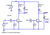
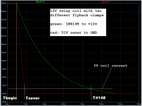
The good news is, you can get most of the available speedup, with a modest zener clamp set to about 4X the supply (thus the coil has Vsupply on one end and 4*Vsupply on the other ... 3*Vsupply across the coil). In this case, a 12V supply and a 51V zener. I don't think anybody has any fear uncertainty and doubt about harming a 12V relay with a 51V flyback pulse.
And I'll bet that member wrenchone's resistor "clamp" (post 32) would give equal speedup with a resistor ratio just a little higher than 4:1, but I haven't fiddled with that option.
Here's the standard diode-across-the-coil arrangement, and the zener-to-ground alternative, side by side. I've plotted the coil current vs time, and drawn a line at the 5% threshold. Relay datasheets generally say the relay is guaranteed to release the armature when coil current falls below 5% of (Vrated/Rcoil). Some say 10% but most say 5%.
_
Attachments
Last edited:
Bad insulation definitely helped to damp high spikes. And relay telephony might need some portion of speed, so...Telephone systems were millions of relays without diodes.
Remember that insulation was not so good then.
Bad insulation definitely helped to damp high spikes
That's exactly correct; in fact, to return again to the power transformer winding as the example, the higher the voltage of the primary winding, the 'better' the insulation to ground (tank, core), an obvious statement. But not necessarily between winding turns, since V/turn is generally the same regardless of voltage or kVA (I seem to recall 8 V/turn being a generalized target for power transformers regardless of size).
However, this improved insulation actually makes the transient behavior correlate more strongly towards traveling wave behavior, such that distribution of voltage is more and more concentrated to the end turns. So higher BIL units, having lower capacitance to ground, are subject to significant problems at the end turns. Various strategies exist to smooth this wavefront. Intentionally increased insulation between those end turns is one of those strategies. Most failure analysis I have done on power transformers occur near the end turns. It quickly cascades to the core, but often starts turn/turn. It can be difficult to determine which occurred first, admittedly.
Therefore, the better the insulation, the more challenging the situation.
Sure, this is taking the case to the extreme when we are dealing with 5V or 12V relays, but in theory the coil can generate thousands of volts, limited only by the passive strays in the system. These strays are either unknown or variable, hence it becomes wise to set a control in the system that is known. The zener idea I think is an excellent option. You can still add the parallel resistor if you want, but at least you know for certain that the zener voltage sets the limit. I would have no problem with a 100V zener without risk to the coil, and you definitely get the advantages of high speed.
One could choose the 300V transistor, unprotected, which has an avalanche voltage, perhaps somewhere near the 600V peak we saw in the scope capture by Mark. Put in a 1000V transistor; curious if the peak increases.... Likely strays begin to take over the behavior, but in practice the transistor avalanche probably has some measure of control over the transient. Since the actual avalanche value is variable, one could come up with a really 'good' transistor and have extremely high peaks, with potential coil failure.
Outwards. With an iron cored coil the coil forces are small compared with the forces between pieces of iron as only a small proportion of flux is outside the iron core.
Lines of flux act like elastic strings that repel one-another. Energy density in a field is proportional to the square of flux density, so spreading out field lines reduces density lowering energy, and shortening lines reduces the total volume of field, again reducing energy.
Lines of flux act like elastic strings that repel one-another. Energy density in a field is proportional to the square of flux density, so spreading out field lines reduces density lowering energy, and shortening lines reduces the total volume of field, again reducing energy.
.....V/turn is generally the same regardless of voltage or kVA (I seem to recall 8 V/turn being a generalized target for power transformers regardless of size).....
Hmmm. Not arguing, but at the hundred-VA size we can't go over 0.1V-0.2V per turn without problems. This value declines, slowly, with core size.
I had a coil exploded in my country house.
A coil in a remote switch, that was not working anymore.
May be from some stupid repair attempt, may be from a thunder lightning, but there was no burn or such traces, may be from an inappropriate operation under 230 V.
For sure the coil made of thin wire had an exploded look with several of them pried out.
Any idea ?
Last edited:
Hmmm. Not arguing, but at the hundred-VA size we can't go over 0.1V-0.2V per turn without problems. This value declines, slowly, with core size.
Will try to look it up, the materials go back 25 years from my previous employer, Waukesha Electric Systems (also under names Hevi Duty, ABB, Magnetek, North American Transformer, ASEA). I believe V/turn is proportional to core area iirc.
A sample is attached. Fundamentally, it comes down to cost. As the size of the xfmr increases in VA, the copper loss becomes more cost-prohibitive than the core cost. So it becomes practical to increase the core cross sectional area in an effort to reduce the number of turns (increasing the V/turn and reducing the amount of copper).
This is in agreement with my experience in comparing small transformers we use in our amplifiers vs large power transformers measured in tens or hundreds of MVA. Small transformers have impedance largely dominated by resistance, whereas large transformers are largely reactive. They increase core size and crank up the V/turn, providing reactive behavior and limiting resistive losses.
Unfortunately I cannot find the 8 V/turn value anywhere; I suspect it was a particular unit I was studying at the time, likely in the neighborhood of 30 MVA base.
Attachments
- Status
- This old topic is closed. If you want to reopen this topic, contact a moderator using the "Report Post" button.
- Home
- Design & Build
- Parts
- Relay coils polarity, why some matter and others dont ?