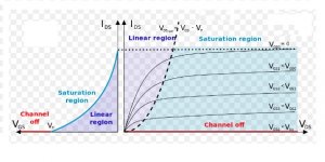
In the resistive part of the usual JFET have a narrow working area. Which is inconvenient....The main idea was to run them in the resistive region where they were very linear.
This zone is the transition from triode to pentode output characteristics. It is much better to use JFET - SIT in the same transition zone. From triode to pentode.
This will lead to the best interaction of the amplifier with the complex nature of the load. The attachment is an example of such a solution.
Pentods "liked" loads an of magnitude below their internal resistance. Triodes - on the contrary. The best will be the "ultra - linear" inclusion.
Attachments
Last edited:
I finally tamed the JFET SiC UJ3N065080K3S.
The optimal current is 400 mA. For three hours of operation, the current increases from 200 mA to 600 mA. I had to install thermal stabilization from two germanium diodes Д7Б (see circuit).
I am very pleased with the sound. High frequencies cut through. Air and volume appeared in the sound. But I had to make a delay in turning on the UJ3N065080K3S.
Rout - 0.78 Ohm. Frequency response: 5 Hz - 0.6 MHz (0 dB).
JFET-only Circlotrons without negative feedback.
Completed amplifier project on JFET UJ3N065080K3S.
Circlotron on silicon carbide transistors. - YouTube
Circlotron on silicon carbide transistors. - YouTube
UF3C170400K3S
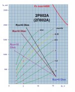
Like the OP, I am a noob who was bored and browsed Mouser's catalog. And I came across this https://www.mouser.com/datasheet/2/827/DS_UF3C170400K3S-1772171.pdf. First thing I noticed is these are not typical mosfet curves. The device is a SiC jfet cascoded with Si mosfet. I see a few designs using the LU1014 in such an arrangement. Could these be a substitute?
Like the OP, I am a noob who was bored and browsed Mouser's catalog. And I came across this https://www.mouser.com/datasheet/2/827/DS_UF3C170400K3S-1772171.pdf. First thing I noticed is these are not typical mosfet curves. The device is a SiC jfet cascoded with Si mosfet. I see a few designs using the LU1014 in such an arrangement. Could these be a substitute?
Here's an early effort using the Semisouth 085 SiC jfets. A similar amp could be built using the United Silicon Carbide SiC jufets, similar in character to the old Semisouth 085 devices. What you get is a partial feedback SE amp that uses feedback to emulate triode behavior in the output device.
"SiC Puppy SE Amp Using Semisouth 085 JFET
"SiC Puppy SE Amp Using Semisouth 085 JFET
Like the OP, I am a noob who was bored and browsed Mouser's catalog. And I came across this https://www.mouser.com/datasheet/2/827/DS_UF3C170400K3S-1772171.pdf. First thing I noticed is these are not typical mosfet curves. The device is a SiC jfet cascoded with Si mosfet. I see a few designs using the LU1014 in such an arrangement. Could these be a substitute?
Τhirdicomplex I think you will find that you are looking at a mosfet cascoded with the JFET: "The silicon MOSFET serves as the control unit while the SiC JFET provides high voltage blocking in the off state". Did you not want them the other way round?
")
- Home
- Design & Build
- Parts
- Power JFETs in production