The impedance that matters is the real part as the imaginary is not disipative. The efficiency of the electronics is a bit tricky as efficiency can't really be approximated by say 90% if the signal has wide dynamic range. The only way I can think of is to do a basic simulation of the amplifier into a LCR network approximating the impedance of the real speaker. Such a simulation would need to include: switching loss, conduction loss and quiescent current and be driven with a real world music signal (or test signal with similar power spectral density). It would be an interesting excersize but I'm not sure how practically useful it would be unless you wanted as small as possible battery pack. As a guide my battery (16s, 20aH, ~1.1kWh) will run my system for aprox 48hrs.
1) A "bass reflex" system is a "phase inversion" system, the output of the port lags the initial signal by one cycle, but is "in phase" with the cone. The decay time of the port is basically the same over it's pass band.@weltersys
1)So, the transient response would suffer due to the long decay time at the port frequency and the over-abundance of energy at this point with poor damping?
2)In which case, if I keep the gain at Fb below a certain value then the advantages of a higher Qts woofer will be able to be heard?
3)Would shifting Fb out of this range or introducing a small notch cut at Fb help?
4)If I understand your last sentence correctly, do you mean for maximum SPL at depth then the 2x10 would be superior, but if I am after transient response (and am sensible with EQ) then 1x12 would be best?
2)The lower Qts woofer may sound subjectively "tighter" than the higher Qts woofers(s) throughout the passband.
3)Lowering Fb would would possibly "help" regarding perceived transient response, but would hurt efficiency. Since efficiency and output rather than extended LF is the goal, lowering Fb would be counterproductive. Hoffman's Iron Law- Low, Loud, Small-pick two (given a limited amount of power).
Regarding power use, the dynamic range of the music has a huge effect- some EDM has a crest factor of as little as 3dB (same as a sine wave) below 100Hz, while the majority of music recorded prior to the "loudness wars" has more than 12dB crest factor. At maximum level before clipping, the type of music played could result in as much as a 10 to 1 difference in battery play time, while the difference of +2 dB is less than 2 to 1.
4) Yes, at least at the depth of an Fb of 60Hz- the 12 might have an advantage if Fb was lowered.
Art
Last edited:
@kipman725
Sounds like a great deal of complexity, unless I'm on the edge of the battery life (which I'm not too much). I have some neat little oled power monitors here, when I build it I'll just check out the average power reading and do it that way.
@weltersys
Thanks for taking the time, again, to explain the physics (or physical effects of it) of the system. It makes much more sense now.
It's a shame this Hoffmans law is a perennial occurrence! I guess more power is always a workaround.
For now I'll stick with 1/6 average power (~7.6dB crest factor). Seems to be middle of the road enough.
-
-
-
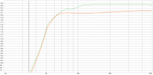
Given that the two systems have more or less the same efficiency around the 60hz LF corner (attachment is 1x12 and 2x10 scaled to the same power) then I would probably rather go with the simpler and ""tighter"" solution, forgoing the 70Hz+ efficiency gain (which will ultimately see less LF boost to hit the equal loudness contours or thereabouts, and will have a slightly smaller impact on battery life).
.. Although, the 12CL64 does easily take the full 600w before even touching Xvar in 45l/60hz.
The question is: Is it worth going for a higher power IRS2092 mono block with a 70v boost converter with a virtual ground? Alongside a little TPA3116D2 @ 20v for the HF section.
Do I need the SPL (realistically), is it worth the extra complexity and decrease in battery life.. !
Sounds like a great deal of complexity, unless I'm on the edge of the battery life (which I'm not too much). I have some neat little oled power monitors here, when I build it I'll just check out the average power reading and do it that way.
@weltersys
Thanks for taking the time, again, to explain the physics (or physical effects of it) of the system. It makes much more sense now.
It's a shame this Hoffmans law is a perennial occurrence! I guess more power is always a workaround.
For now I'll stick with 1/6 average power (~7.6dB crest factor). Seems to be middle of the road enough.
-
-
-
Given that the two systems have more or less the same efficiency around the 60hz LF corner (attachment is 1x12 and 2x10 scaled to the same power) then I would probably rather go with the simpler and ""tighter"" solution, forgoing the 70Hz+ efficiency gain (which will ultimately see less LF boost to hit the equal loudness contours or thereabouts, and will have a slightly smaller impact on battery life).
.. Although, the 12CL64 does easily take the full 600w before even touching Xvar in 45l/60hz.
The question is: Is it worth going for a higher power IRS2092 mono block with a 70v boost converter with a virtual ground? Alongside a little TPA3116D2 @ 20v for the HF section.
Do I need the SPL (realistically), is it worth the extra complexity and decrease in battery life.. !
Attachments
yeah I think if your estimating 7.6dB crest factor into a resistor your actual battery life is just going to be better than your estimate so no need to worry.
I'm running 36V amps and think it would be worthwhile going up to 70V for your bass section but you should also run the other sections off 36V amps")
I'm running 36V amps and think it would be worthwhile going up to 70V for your bass section but you should also run the other sections off 36V amps
Do you know of any suitable 70V amplifiers? I assume your 800w design could be suitable, even if it doesn't strictly exist yet!
I haven't found an IRS2092 based design that fits the bill yet. Idle current seems quite high, getting +/-70V is a little tricky, and according to online sellers they have a narrow voltage input range (can't run natively off battery to save some joules).
It's a shame the TPA/TAS series end at 50v (or 56.5v if you want to really push the datasheet).
the only single supply high power amps I am aware of are the sure electronics modules (I had the same issue finding them):
High power single supply amplifiers?
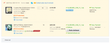
On my amp front I have delays due to Chinese new year on producing my prototype to test if I can get these tiny chip amps to a higher power level by bridging them and running them on an aluminum board. I'm using IR4301 to try and get the cost and size as low as possible per channel. I am targeting 500W into 4ohm (internally bridged amp) but in the further future I would like to make a discrete add on bass amp module.
High power single supply amplifiers?
On my amp front I have delays due to Chinese new year on producing my prototype to test if I can get these tiny chip amps to a higher power level by bridging them and running them on an aluminum board. I'm using IR4301 to try and get the cost and size as low as possible per channel. I am targeting 500W into 4ohm (internally bridged amp) but in the further future I would like to make a discrete add on bass amp module.
Attachments
Hmm, I saw that Tamp on my same search. I ignored it due to it being 'old tech', haven't used tripath since TK2050s.
Seems I'm following in your footsteps with the search..
That price for the Tamp is definitely on the high side and the specs overkill for what I need. Although the mono one looks nice, $250 is insane!
Definitely keep me updated with the IMS pcb IR4301. I think there's a genuine gap in the market for these single rail chaps, I'd buy one!
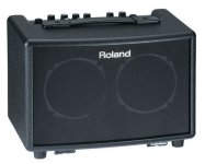
I think it's hard to beat the following, Roland AC33. I am so impressed with this unit. I bought it to do some busking gigs. I flew it to another state to play guitar instrumentals at a church wedding in fact - filled a pretty big space.
One can mix an instrument and a vocal, ie two channel. It also has a 1/8" jack on the back with settable level so one can play along with recorded music. I bought a simple bluetooth receiver mounted on an 1/8" plug so I can play my phone through it.
The battery pack on the back holds 8 AA cells, is very high quality, reliable. and is most well executed mechanical design I've ever scene in a portable piece of equipment.
Perhaps you have no use for the "Chorus" affect but the reverb is superb and the unit is stereo to boot. Ohh and it has anti-feedback built in - quite indispensable for live music I'v found.
I know it's not a "makers" product but you could use it as a benchmark for comparison. They often can be had on the used market for less than $250.00.
Attachments
Last edited:
Campsquire,I think it's hard to beat the following, Roland AC33.
I know it's not a "makers" product but you could use it as a benchmark for comparison.
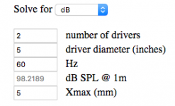
As a benchmark for comparison, the 2x5" Roland AC33 at 60Hz could put out (at best) 100dB at one meter, while the designs the OP is considering are almost 20dB louder.
Art
Attachments
Thanks for the input campsquire! It's always impressive to me how a well designed unit can create depth and volume beyond their stature.
As mentioned (I really did enjoy your comparisons Kaffiman, lol) it's a different ballgame in terms of LF output.
For comparison, I am currently using dual 5" units in a different project (Faital 5fe120) in 7.5L tuned to 75Hz which is 15dB down at 60Hz and -20dB below 50Hz compared to the single 12" in 45L tuned to 60Hz.
Interestingly, because of the tuning there's 'only' 3dB sensitivity difference at 100Hz, for a 3.2x SD increase.
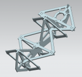
Been chipping away at the structural design of the unit here with the 9mm poplar ply.
Managed to achieve global stiffness and modal response performance "equivalent" to a 35mm birch ply box or 20mm with basic internal bracing. Could go further in FEM to reduce mass, but realistically there is less than 100g of optimisation left.
Slightly back to front, the internal bracing is an initial subassembly, which the enclosure is then built around. With overbuilt external panels and a trimmer to take care of tolerance - I'm hoping it'll be a piece of cake to build!
A ton of details to work out now - but happy with the overall structure strategy.
Attachments
Been chipping away at the structural design of the unit here with the 9mm poplar ply.
Managed to achieve global stiffness and modal response performance "equivalent" to a 35mm birch ply box or 20mm with basic internal bracing. Could go further in FEM to reduce mass, but realistically there is less than 100g of optimisation left.
Slightly back to front, the internal bracing is an initial subassembly, which the enclosure is then built around. With overbuilt external panels and a trimmer to take care of tolerance - I'm hoping it'll be a piece of cake to build!
A ton of details to work out now - but happy with the overall structure strategy.
have you considered making the back and sides out of curved laminated ply to increase sitffness?


Getting a little mixed up where with calculating power.. Seems I have been underestimating the effects of impedance on the output.
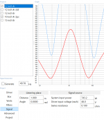
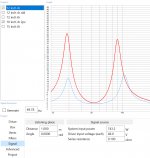
I have been entering values into 'system input power' (280w@4r off TPA3255 datasheet), but it seems that entering 'driver input voltage' should have been done instead.
In this case, with 48v (Assuming there's a small drop from 50v supply), the system input power goes up to 743W (see attached).
Is this correct? If so, that makes my 80mm ports woefully undersized (vent velocities up to 50m/s!) and the excursion also goes through the roof away from port tunings (over XVAR above and below tuning frequency).
Good news is that maximum SPL increases significantly, and the 15CL76 (if I can shoehorn it in) becomes a viable option even. Otherwise, the two 10s may be reconsidered.
Attachments
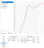
The "System Input Power" in WinISD refers to the loudspeaker system, not the total amp+speaker package. It is calculated from the stated Driver Input Voltage and the driver's predicted minimum impedance, whatever frequency that occurs at. Driver Input Voltage is therefore equivalent to the amp's Output Voltage, rather than it's supply voltage.
So, if your design has a Zmin of 5 ohms at 300 Hz, but doesn't drop below 6.5 ohms in the subwoofer region, the calculated input power may seem unexpectedly high.
In your case, 280W @ 4R is an output voltage from the amp of 33.46V if my arithmetic is right - might that have something to do with your 743W seeming so high?
HTH,
David.
Hi David,
Cheers for the reply,
I'm not sure it still makes sense to me though, electronics has never been my strong suit!
So, the 743V is derived from the Re: 3.1R, which works out with me.
However, if the datasheet dictates that the amplifier puts out 280W@4R does this mean that the amplifier with a PVDD: 50v only has an output of maximum 34V?
This doesn't tie up with what I am reading online for BTL amplifiers, whereby the full input differential is on the output, minus O/P losses.
- Home
- Live Sound
- PA Systems
- Backpack challenge