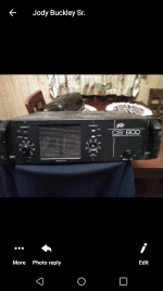
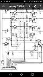
Hello all im new to this forum to join but have read alot learned alot.Thanks . New problem i have is a Peavey cs-800 3u just like the cs800x but no x denoted. I need a schematic because it has a few shorted output xsistors.A shorted triac,the power on triac and a shorted bridge rectifier. Theres so many different cs800 models and its hard to get the right infobill post a pic here of it. Thanks if anyone can email me the right schematic.I have not heard back from peavey.Let me know if i show my email here if any of you fellas have it to send
Attachments
Use the CS800X. The difference between the X and non-X versions is only on the spec sheet. The X was added when they tested the amps and felt they could safely rate them down to a lower impedance load. The circuits are identical.
PV is usually very responsive, but you are in the USA, and as always, a phone call is the most effective. Most guys who call report it takes about 10 minutes for the files to arrive.
If you do communicate with them, call this a "wind tunnel" version.
PV is usually very responsive, but you are in the USA, and as always, a phone call is the most effective. Most guys who call report it takes about 10 minutes for the files to arrive.
If you do communicate with them, call this a "wind tunnel" version.
The schematic is also available 24/7 on eserviceinfo.com
Search cs800x. You don't have to be a member.
The output transistors are MJ15024/25, but if you replace them all you can use cheaper MJ21193/94. Don't forget to check the emitter resistors.
The drivers also are usually blown out by the current out the base line of the outputs. You can use mje15032/33.
The predrivers can be MPSA06/56 or MPS8099/8599.
The triac is generic, I used a 600 v rated one for the on/off one. BTB16-600cw. The sense "sbs" on the crowbar circuit blows sometimes, I use the powerex bd08s from newark farnell. They sometimes have J174 DDT transistor but nobody has the ca3080 transconductance amp IC.
Last edited:
Look for the dual diodes inside a little dashed line box. Like CR109? And three other diodes asociated.
Honest, CS800X is the right drawing.
Look at the schematic, 73180 are the PNP outputs.
It is an MJE350, not a je350.
SAC187 is a four quadrant triac. I forget what I used to use in place of them, but it was something common from Mouser. You can order them from Peavey, and they will send you whatever they use in their place.
If the SAC187 is shorted, just remove it. The amp will function without it while you continue repairs. We can replace it after the amp is working.
The big on/off triac is something like a Q4025 or Q4040. That is a 400v (or higher) and 25 amp or 40 amp.
ok thanks again ive been researching .I fixed a qsc 1400 but seemed less complicated.My mains triac seems ok it measures good but ill wait till last to see if it operates right..The items that are shorted are a je350 motorola #839 to126 that was on the heatsink .Standing up.There are 4.Also the sac187 and two 70473180 opts.Been checking other resistors ,seem ok.Btw im kind of a newbie.All i have is a hakko 951 and a ut33a dvom and an esr meter The old kit form ones.The dick smith one.
I,ll be studying the schem more guys.
By the way i thought this amp was quasi comp but it looks like the qsc,full complementary if im right.I need to build a DBT box but im low on funds lol.And no junk heater element layin around right now.By the way this peavey xformer could be used as an isolation transformer maybe.It outputs 115vac on secondary.When i tested it by itself.With 120v in on primary.
The crowbar triac and predriver transistor part numbers are in post 3. If your supplier hates On semi, you can use 2n5401 and 5n5551 but they cost more for more Vcesus. The SBS (sac187) can be replaced by two 1.5 watt or bigger 7.5 v zeners back to back.
The little loop on the main heat sink is a dual diode, which may not read on some DVM if good. Drops 1300 mv. It's in a dotted line box on the schematic, and between pins 1 & 2 on the interboard connector on the power board. You can't buy them except from Peavey,and that takes a phone call and a long hold. You can use a red LED (10 ma or 20 ma kind) instead and insulate the lead that flys around because it points the wrong way. You'll need some heat sink compound on that heat sensor.
If it blew a predriver, the op amp may be toast too. 4580 is available at distributors from TI & NJR, but a 4558 will work if not sound quite as good.
Often the VI limiter and all its sense resistors and transistors blows up. That is the two transistors in the middle of all those caps & resistors right in the middle of all the drive lines. I'm not sure what it is good for when working, but will short out drive lines if it is all shorted. Some kind of old fashioned speaker protection for people that use megadeath crunch pedals (square waves) on their guitar. DDT backs off the high frequencies from those signals, too.
These cs800-x sound really good when working right. Even at 1/8 watt which is the base level sound in my living room. The one I bought also played a crowd of 300 in a parking lot, the previous owner told me. I fixed mine with a dvm, and an analog vom which shows music through the low level stages on the 20 vac and 2 vac scales. On an analog VOM you have to put a .047 uf (400 v) cap or similar in between the negative probe and the speaker ground, to make the AC scale not read on DC signals. You'll never catch an op amp whanging to rail because of a bad solder joint on the input, with a dual slope method DVM. They are too slow, they average the signal over a second or two and miss fast events.
BTW Peavey PA amps have a "flying ground" which means the speaker return has no reference to case ground or AC neutral. Has something to do with the bridge function, makes it cheaper. The Power supplies for the two channels are not related to each other, have separate speaker grounds that fly around separately. When debugging the circuit live, use the speaker ground terminal of the banana jacks for your reference.
I used a room heater element as my 120 vac ballast, 100 w bulb was too small to allow the +-16v to power up. Had nice spade lugs on it that matched the spade lugs on the power entry in the back. Room heaters are always blowing the tip over switch, lots of them in the garbage this time of year in the US.
Last edited:
There are six 1000 ohm resistors on the main heat sink to sense for the VI circuit. My PV-1.3k amp all of them were vaporized, hard to tell what they were. They are pin 6 & 8 if I traces the lines right.
There is a stack of temp sensor diodes per channel, between pins 3 & 13. The loopy one buried in the heatsink is the dual diode, cr103. Three regular diodes, probably near the driver transistors.
You are sliding the schematic page to the right to see the output board? Usually they are stacked vertically, but not on this eserviceinfo.com one.
BTW DON'T install the crowbar triac until everything has worked properly for several hours without the AC line resistor. You can blow several of them as you find more & more problems. Like I found some of those green cylinder caps were shorted or open, in the VI limiter. Also some of those little 0.1 uf tan caps sprinkled around the op amps.
The schematic shows which diodes are which type, the layout drawing shows where each is located. Should be no question.
Peavey does use flying rails on numerous models, but this is a CS800 which does not. The "output" bus goes through a relay to the speaker, and power supply commons are grounded.
Are you looking at the CS800X drawing set?
Peavey does use flying rails on numerous models, but this is a CS800 which does not. The "output" bus goes through a relay to the speaker, and power supply commons are grounded.
You are sliding the schematic page to the right to see the output board? Usually they are stacked vertically, but not on this eserviceinfo.com one.
Are you looking at the CS800X drawing set?
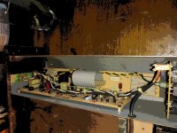
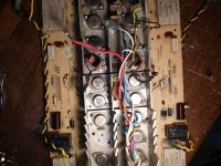
I cant tell which one of the diodes is the dual diode guys.My heatsink has six of those diodes looped down in the heatsink.The one i think is the duouble diode,well it looks the same as the others doesnt read shorted or have a voltage drop either way on diode test.That one part of this amp confuses me.Why doesnt the double diode look different?And theres not jus one diode loop on my heatsink there are six.But hey ill keep on truckin studying the schematic.
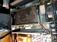
I have a new diotec bridge rec coming ,its shorted on the dc output side .No testing till i get that.I'll try to post a pic of the heatsink .Remember im jus doing this in my back garage,no claims to pretend im that experienced lol.But i learn lil by lil.
I have a new diotec bridge rec coming ,its shorted on the dc output side .No testing till i get that.I'll try to post a pic of the heatsink .Remember im jus doing this in my back garage,no claims to pretend im that experienced lol.But i learn lil by lil.
Attachments
I've got a PV-4c output board out on the bench, and my double diodes are reading 1.502 v and 1.485 v forwards. The 1n4003 should read between .480 and .700 v forwards.
You've got two channels, doesn't the 13886 read correctly on even one of them? There are 4 diodes in the heat sense string at the bottom of the page, 3 of them are 1n4003 and one is the double. My CS800s is supposed to have a similar circuit but I'm not in the mood to take it apart just to look at this. Super experienced Enzo will know exactly, but he spends a lot of days away from the internet since he retired.
I expect one of the 1n4003 to be located near the drivers, which are the transistors with the base connected to pins 3 & 12. The double diode ought to be out in middle of the main output transistor area since that is where the real heat builds up.
When two double diode were blown in my PV-1.3k some kind person in illinois mailed me two that were from a scrapped unit. But nobody is talking here. Peavey sells them still. OTOH you could drill the heat sink a little bigger where the bad one is, glue in a red LED with heat sink glue, and shrink wrap the two leads around to solder in the board. Unfortunately heat sink glue is about $20 a tube.
You could alternately drill & tap a 4-40 or 3 mm screw hole, and screw on a transistor like a BD139 or MJE340 on a heat insulator pad. Then it takes two more resistors to get it to drop 1.48 v when cold as a Vbe multiplier. you've got to fiddle with a pot to get the exact value, then replace it with a fixed resistor. You can't leave a pot in permanently, the wipers oxidize eventually and make too much voltage drop which makes way too much idle current on the output transistors overheating them. To see the schematic of a vbe multiplier look at one of the NAP140 or 150 threads percolating on solid state now. The Vbe multiplier is between the bases of the driver transistors. Peavey's are suspected to produce crossover distortion occasionally cold at low wattage. A carefully adjusted diode stack or Vbe multiplier could solve that, but adjustment costs money in labor charges, so they didn't do it. Not important at 300 W/ch. To make them a hifi amp, fiddle with the diode stack until the crossover distortion at 1 W is gone. At least the later models with the 4580 "good" op amp.
Peavey didn't mark these double diodes with anything, which makes them a not ISO4001 compliant company. The insertion operator that put the special diodes in had a whole box of them, no confusion there.
Last edited:
- Status
- This old topic is closed. If you want to reopen this topic, contact a moderator using the "Report Post" button.
- Home
- Live Sound
- PA Systems
- Need schematic for cs800 but not s or x. Looks like the x one.