Jamo concert 8 crossover
Hi Dave,
I am not sure if your intention is to improve the crossover 'as is' in the Concerto or to make your own crossover. My idea was to change the caps
because this looks as an easy job. But as I already mentioned I was not able to find any relevant info. So I opened the speaker by removing the mid/bass driver and was ''stunned'' by the complexity of the crossover inside. So I decided not to mess with the crossover. I use the Concerto in
my second system in my bedroom. In my main system in the living room I use the Usher BE-20. I am actually very fond of those Concertos in particular with vocal music. But they are not perfect so I intend to try the Revel ultima gem insteade. My bedroom is 5x4 m so I have no need for bass below 40 Hz. I need also to add that I was much impressed with
the mid/bass driver. Besides it still looks as new after 15+ years (?).
Regards,
Nikola
My intention was to improve the system response, whether by tweaking the existing crossover (retaining as many original components as possible) or completely re-designing it. In my opinion, the latter was of much more benefit. It is a good system, but it can be improved when one is not constrained by the cost of the overall crossover.
Personally, I was more impressed by the box/baffle than by the drivers/crossover, although the latter are excellent on their own, despite my concern with the midwoofer.
Dave
Personally, I was more impressed by the box/baffle than by the drivers/crossover, although the latter are excellent on their own, despite my concern with the midwoofer.
Dave
Hi Dave, The most of us are, alas, not at your technical level. What we can do is solder better caps with the same values in place of the old one. I assume that all those resistors in the crossover are meant to correct the impedance and/or tame the mid/bass driver (hard) mebrane? To change or mess with those is to complex for us.
My estimate reg. the Jantzen superior Z caps is that they are 10x larger then the original . I don't believe that anyone is willing to spend a fortune to improve the crossover but those Jantzen capacitors are not very expensive. So if those caps will
make some improvement they can be an good option for amateurs like me.
BTW is my assumption correct that to remove the crossover one need to first remove
the (bi) wire nuts from the connectors on the outside and then pull the crossover out
from inside Those wire connectors are fastened (and soldered) on the crossover print . So I assume that this is the only way to get the crossover out.
Regards,
Nikola
It's been about 6 years since I looked at this, so my memory is very foggy on details. I bypassed the crossover to run the system using the Digital Filter. The crossover is probably still mounted inside. However, I do have the OEM crossover schematic as I entered it into SoundEasy. I've downloaded a copy for this post. I believe it is accurate.Hi Dave, The most of us are, alas, not at your technical level. What we can do is solder better caps with the same values in place of the old one. I assume that all those resistors in the crossover are meant to correct the impedance and/or tame the mid/bass driver (hard) mebrane? To change or mess with those is to complex for us.
My estimate reg. the Jantzen superior Z caps is that they are 10x larger then the original . I don't believe that anyone is willing to spend a fortune to improve the crossover but those Jantzen capacitors are not very expensive. So if those caps will make some improvement they can be an good option for amateurs like me.
BTW is my assumption correct that to remove the crossover one need to first remove the (bi) wire nuts from the connectors on the outside and then pull the crossover out from inside Those wire connectors are fastened (and soldered) on the crossover print . So I assume that this is the only way to get the crossover out.
Regards,
Nikola
The impact of any specific component such as resistors is usually more complex than can be described in a few words. You'd need to see the changes in the response with changes in the magnitude.
Dave
Attachments
Dear Dave, Our member Corelement asked the question ''why a lot of people have been modifing the crossover?'' Well I was searching all over the 'glob' to find any of
those people and the only one I deed find are you. Because of my 'technical capabilties ' I would not use the optimistic expression ''modifing'' but rather more modest expression ''substituting'' the old caps with something more, say, ''modern''.
While the available literature about the caps is mind-blowing it was relativ easy to find the right kind. That is to say very good and , who will believe this, pretty cheap.
The Jantzen superior Z caps 4,7 uF = 18 euro. The Z silver (much better?) 4,7uF=24 euro. To be honest I thought that the crossover schematics was wrong. I thought namely that those 4,7 uF are used for the tweeter while the other two of 6,8 uF and
10 uF were 'of course' for the mid/bass driver. From your 'picture' I see the crossing
by about 2000 Hz wich is pretty low for a tweeter. In this sense I understand the 3 th order (18dB) protection for the tweeter. But like you i think that the mid/bass driver
needs no so much protection as well to be tamed because those hard membrane have
nasty resonances. So my idea is to substitute only the caps for the mid/bass driver
which imply 4 x superior Z or (even better) 4x Silver kind. By the last mentioned one
can then show off with real silver in his Concerto's.
Regards,
Nikola
2000Hz is not low for a good tweeter. I would say that the crossover is 2500Hz, not unusual, especially one of the quality of this Seas unit. My final crossover was around 1900Hz, but then I seldom drive a system as loud as many would. A manufacturer has to take some possible abuse into account to protect it.
I am confident of the crossover schematic. I ran a quick test in my new design program. A typical third order electrical on a tweeter (with the L-R 4 acoustic response) often has the second cap somewhat (or very much) larger than the first one. Swap the caps and the summed response is definitely bad.
I don't comment on cap quality. I'm not one to put emphasis on this, other than to use good quality caps, avoiding non-polarized electrolytics, except for certain 3-way woofers due to the large values sometimes required.
Dave
Dear Dave, Thanks for your explanation. I am aware of the respose from the ''technical
guys'' to the notion of the ''sound of capacitors''. To them the specific technical requirement for a given task are all that counts. If they are polite like you they will say: ''I have no opinion about the sound of capacitors.'' The other will say: ''this notion make no sense to me''. But one of the attractive possibllities of our hobby is,say, ''messing with components''. There are many people who go to the church and
ask all kind of things from the Almighty. In our hobby even the atheist are allowed to
hope that some illusion may become true. Anyway this is my hope with those Jantzen
capacitors while the investment is certainly bearable. If I only knew how to get this
damn crossover out of the box(grin).
Regards,
Nikola
I decided to bump this old thread,mainly because dlr's measurements on post #24 are very helpful in order to modify the crossover circuit of JAMO's Concert 8.I am not saying that the designer was incompetent ,but cost reduction(I suppose) and home theater "domination" of the era have resulted in tilted (or elevated) highs.After much search and reading on the net(I started with AllenB's great tutorial) I came up with some ideas concerning the crossover,which I want to discuss with other members,hoping to reach to an end!
This is the only comprehensive test of the aforementioned speakers I have found so far:Jamo Concert 8 and Concert Center Speakers and the frequency responce curve,both in anechoic chamber and in room confirms listening tests (like this one: Jamo Concert 8 / Concert 11 - Outdoors Listening Test [English]) and my personal opinion.It seems that,lowering tweeter's output by 3-4 db as well as woofer's around 1 kH,will get things into balance.A change also of the crossover frequency to something around 2 kH will be beneficial. Since I lack the theoretical knowledge and measuring equipment to design a new cross in details,I searched the net and discovered two ready-made high-pass suitable crossovers for the tweeter,presented in the DIY2000 speaker design contest by Dennis Murphy and Jeff Bagby.However, the tricky part is the crossover for the woofer Seas Excel w17e jam,special made for Jamo,identical to the commercial Seas unit,but with a different resistance,4 ohm instead of 8 ohm.
Hello Kimon,
The suggestion of lowering levels of the woofer at 1 kHz and lowering tweeter levels by 3-4 dB's seems spot on. Have a quick look of DLR's measurement of the original speaker and it becomes pretty obvious this is a sub-optimal x/o design.
The designer opted for only minimal Baffle Step correction, and to make things worse, the somewhat rising woofer response, which is matched by a similar trend in tweeter SPL.
The woofer L of only 1 mH is already a give-away in this respect, although the woofer is a nominally 4 Ohm unit. Furthermore, the 5-6 kHz peak is insufficiently sucked-out.
Correct the BSC, and make the woofer flat as of 100-150 Hz, matched with a flat tweeter crossing over at 1800 Hz or so, and you will have a very nice system.
and thank you for answering.This is my opinion too,and I suspect that the nicely curved front baffle makes things worst(just the opposite of what happen with women curves!).I am inclined to use J.Bagby's high pass crossover for the Excel T25 tweeter found on this page: DIY2000
Last edited:
So, we are done messing with the high pass.What about the low pass?Sadly, there isn't ready-made solution.In order to achieve full BSC I am thinking to halve the cross frequency from 2500 Hz to 1250 Hz by doubling the values of L and C: 1mH becomes 2mH and 4.7μF, 10 μF.Will it works?Ah, and something peculiar about Jamo's crossover:the existing values L and C are well chosen for a 2nd order L-R or Bessel crossover at 2500 Hz,but for an 8 ohm speaker.Any explanations?

This looks a very familiar speaker, like the SEAS W15CY001 that Troels worked with here:
SEAS 5INCH
Only difference is the 4 ohm impedance of the drivers.
Here's dir aka Dave's analysis:
And your current modification:
I can see where that is coming from, with the Troels Gravesen style LCR presence notch around 1kHz. It possibly is a better sounding way to do things with these sort of filters.
An almost identical 5" AL130 speaker crops up as default in Visaton Boxsim: Software | Visaton
All you do with 8 ohm drivers is change the 4 ohm 1mH/10uF bass filter to 1.8mH/6.8uF whilst preserving the vital 5kHz metal notch intact. It ends up in much the same place.
Take out the 2.2R R3 on the tweeter, and you get something that works with an 8 ohm tweeter.
That's just modelling tricks. I'd think you need to increase 1mH to about 1.5mH and reduce the first simple R1/C1 shunt to 1R and 2.2uF. That should increase the downward bassmid slope.
R2 then increases from 2.2R to about 4.7R for about 3dB tweeter level reduction. Simple as that. I don't think changing the crossover point lower will really help.
Well, you did ask!")
SEAS 5INCH
Only difference is the 4 ohm impedance of the drivers.
Here's dir aka Dave's analysis:
And your current modification:
I can see where that is coming from, with the Troels Gravesen style LCR presence notch around 1kHz. It possibly is a better sounding way to do things with these sort of filters.
An almost identical 5" AL130 speaker crops up as default in Visaton Boxsim: Software | Visaton
All you do with 8 ohm drivers is change the 4 ohm 1mH/10uF bass filter to 1.8mH/6.8uF whilst preserving the vital 5kHz metal notch intact. It ends up in much the same place.
Take out the 2.2R R3 on the tweeter, and you get something that works with an 8 ohm tweeter.
That's just modelling tricks. I'd think you need to increase 1mH to about 1.5mH and reduce the first simple R1/C1 shunt to 1R and 2.2uF. That should increase the downward bassmid slope.
R2 then increases from 2.2R to about 4.7R for about 3dB tweeter level reduction. Simple as that. I don't think changing the crossover point lower will really help.
Well, you did ask!
Attachments
Last edited:
When you are trying to tweak a loudspeaker that is already good, the opportunity for improvement is slim, and the improvements to be had might come with a compromise, such as Dave's case, where he stated that he does not play loudly.
It is best to approach such a re-engineering effort with the right tools: ones that allow you to make informed decisions. I recommend at the minimum, getting a measurement system up and running. Not only for on-axis measurements, but also for distortion profiles and off-axis radiation. Also, keep in mind the environment that it will play in: you would have to be more critical of off-axis performance in an environment that is reflective vs one that is acoustically absorbent. Also, the amount of baffle step to dial in can be chosen according where you will be placing the speakers (e.g., free standing vs desktop).
Also note that Dave mentions SoundEasy's Digital Filter. This is a crossover emulator that allows you to listen to your crossover without having to build it physically, so you can tweak to your heart's content and not waste a small fortune on parts.
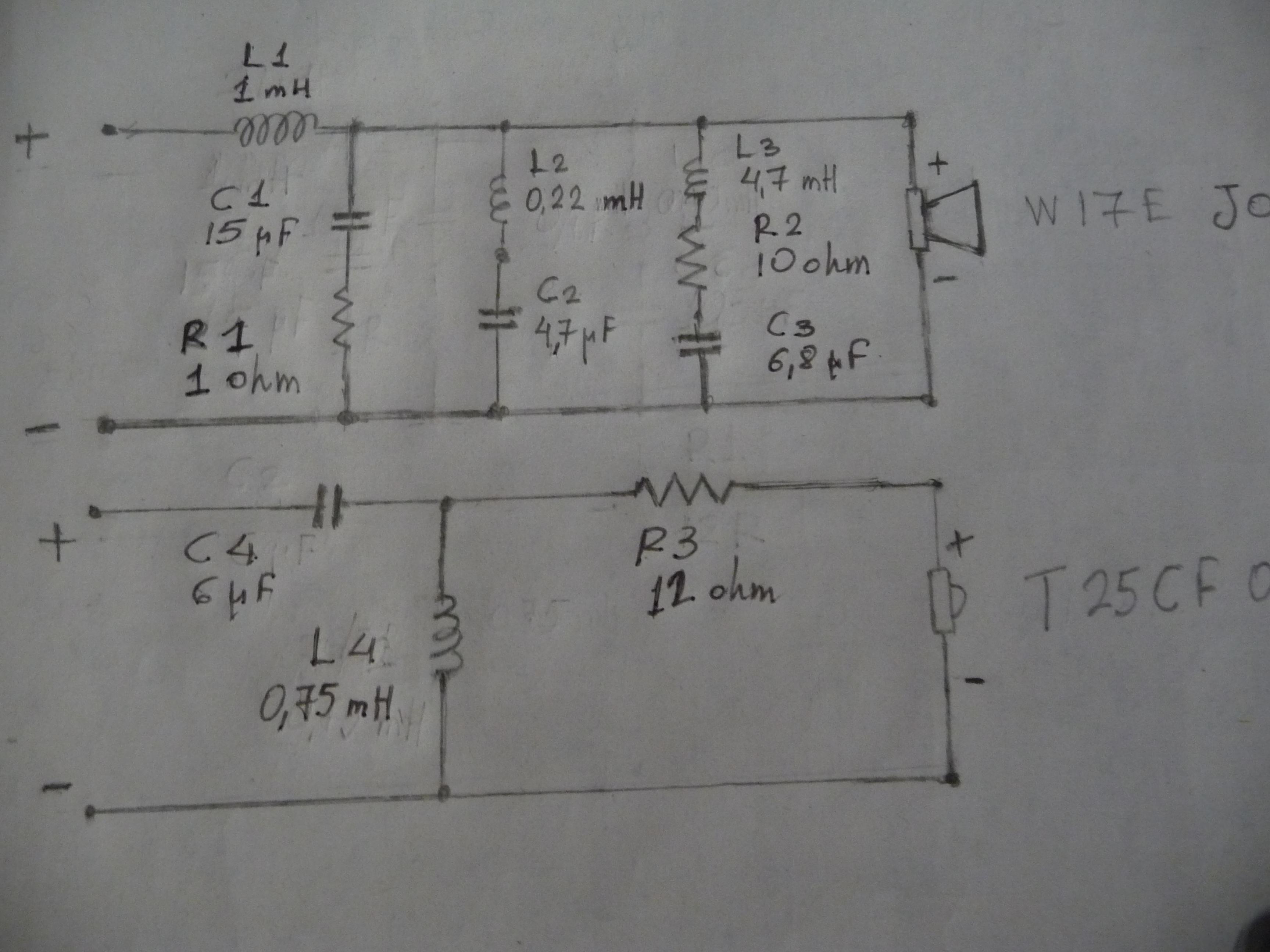
Steve and Shaun I am much obliged for your friendly advices.I have been searching a lot in the Net last year, looking for crossover solutions that one could use to couple W17E jam (woofer) and T25CF001 (6 ohm tweeter) in a more "agreable" way than that of the designer of JAMO Concert 8 / D 830.Both drivers are made by SEAS,the latter (tweeter) being still in production.Woofer is specially made for Jamo,and it is identical to the W17E 002 with the exception of the resistance:it's 4 ohm,not 8 as the normal production unit.That been said,finding crossover for T25 is fairly easy.I have chosen Jeff Bagby's solution,presented in the DIY2000 contest.It's 4th order,with Fc at 1750 Hz.The only disadvantage for my task is the rather big resistor in series with the speaker (12 ohm),that reduces tweeter's output to 83-84 db (according to Jeff's simulations).I'm planning to replace it with a 9-9.5 ohm one,in order to reach 85-86db.My concern is if this change will affect drastically Fc.I have been told no,not significantly.
On the woofer branch I tried only minor changes. My goal is to reach 85db.I added the LRC circuit to have full BSC and I increased the shunt capacitor from 4,7 to 15 μF in order to achieve a 2nd order filter(i.e. to increase the slope and have an Fc around 1300 Hz.The answer for this lies in W17E's distortion profile:it has an increasing 3rd order HD after 1300Hz,with a peak at 1800Hz.Thus the low Fc).Should I omit the 1 ohm resistor?According to online calculators,1mH/15 mF gives a L-R or critical filter, 1mH/21mF a Bessel and 1mH/31mF a Butterworth one.Any opinions about which one to choose?(I use mh-audio.nl calculators).
On the woofer branch I tried only minor changes. My goal is to reach 85db.I added the LRC circuit to have full BSC and I increased the shunt capacitor from 4,7 to 15 μF in order to achieve a 2nd order filter(i.e. to increase the slope and have an Fc around 1300 Hz.The answer for this lies in W17E's distortion profile:it has an increasing 3rd order HD after 1300Hz,with a peak at 1800Hz.Thus the low Fc).Should I omit the 1 ohm resistor?According to online calculators,1mH/15 mF gives a L-R or critical filter, 1mH/21mF a Bessel and 1mH/31mF a Butterworth one.Any opinions about which one to choose?(I use mh-audio.nl calculators).
Last edited:
OEM crossover and files in WinPCD
These measurement files were from 2007 when I started working with the system. I took a few minutes and found the PCD session files (this was before I started work on WinPCD). Those can be imported into WinPCD, making an easy transition, but the measurement files must be manually imported as PCD didn't save that info in the session file as does WinPCD.
I used the AC Offset section in WinPCD with the minimum-phase version of the files and set up a session file in WinPCD. Double check the values, but I'm fairly sure that they are for the OEM crossover. You should add in estimated or measured inductor resistance values for any that may be missing. WinPCD has entries for some inductors that aren't in PCD which was due to the limitations Jeff had with Excel.
I've attached a zip file with all of those original measurement files and a WinPCD session file for the OEM version. The measured sum of the two raw drivers is included as well. This was used to determine relative acoustic offset as used in the program for the specific driver minimum-phase files provided.
I have an update to WinPCD to fix a couple of small bugs and export of the polar measurements for use in a soon-to-be-released polar plot program, but for now use the current WinPCD version if you care to.
Dave
p.s. The woofer SPL below 100Hz may be a bit off. I had stuffed the box and am not sure as to when I made the near-field measurements used to splice onto the woofer far-field. In any case, it's not really important for use in designing a crossover. The full baffle step is taken into account.
Attachments
Last edited:
One more observation. I suspect that the lack of full baffle step compensation is for two reasons. One being that it will greatly reduce the overall sensitivity of the system to do so. The other is that it is more likely that these were intended for smaller rooms as might be found more often in European settings where the small room will help to compensate for that and/or differing taste in bass response vs. US preferences.
Dave
Dave
- Home
- Loudspeakers
- Multi-Way
- Jamo D830 (Concert 8) crossover