Hi all
Thanks in advance for any suggestions.
I tried to upgrade components in my PMC FB1 network and now have no HF.
The tweeter works fine, checked.
I checked for dry joints, breaks, damage etc, all fine
Checked resistors, fine
Checked inductors with continuity test, fine.
Desoldered and re fitted original comps, no change.
Something has gone wrong and I can't find it.
Can anyone suggest a method of checking the network using only a basic mm?
ty
Hi Mark
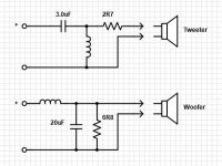
I'm changing the network to FB1+ specs to change the hard dome tweeter to a soft.
Its simply removing the original 3.0uf cap replacing with a 3.3.
The resistor 56ohm is an addition.
Whilst in there I've swapped like for like using closer tolerance parts 2% instead of 10%
I removed 1 part at a time installed the new then moved onto the next then soldered all in one go.
When I had no output I removed the 56ohm and checked.
Next I checked for bad joints, resistor values and continuity.
Then I removed the new cap and resistor replacing with original.
Still nothing.
Is this x-over soldered point to point or does it have a printed circuit board? And where is the input at. I don't see it in the pdf file. Changing the cap from 3.0 to a 3.3 won't make any discernable change in anything unless you are swapping up to a metalized poly cap and getting rid of an electrolytic cap.
If you have put an electrolytic cap in make sure it is a NON- polarized type or it won't work. Check and see if there is a + mark on the cap indicating polarization. If so get rid of it and get a metalized polyprop cap instead.
What is the purpose of the 56ohm resister? 56 ohms is a lot of resistance to put into a x-over so I was just wondering what it was for.
What is the purpose of the 56ohm resister? 56 ohms is a lot of resistance to put into a x-over so I was just wondering what it was for.
Good point - I assumed it was for using in parallel in high pass ..but if wired in series by accident?
The pdf suggests its a PCB to me
Last edited:
That's what I am assuming but who knows it could be a perforated board so I thought I should ask. I suspect there is a polarized electrolytic to blame.The pdf suggests its a PCB to me
My method for checking for continuity is this. I use a simple ohm meter to measure resistance between two adjacent legs of components that are in chain, if the measure is 0 then the two components are soldered correctly, if the value is non-zero then there is a problem.
Imagine a simple 1st order HP cap with a single padding resistor before it. You need to measure between the speaker + terminal and the leg of the resistor facing the terminal, then between the other leg of the resistor and the leg of the cap facing the resistor, then between the other leg of the cap and the tweeter + terminal, and finally between the tweeter - terminal and the speaker - terminal.
Ralf
Hi all
Sorry for not replying it seems I don't get notifications for replies?
The crossovers are both updated and working. The purpose of the journey was to rework the covers to swap out the harsh sounding metal dome to a silk dome. The changes to the network also dropped the cover point from 3khz to 2.5khz.
The original components were all bennic ceramic resistors and electrolytic caps. The new crossover calls for removing the 3.0 cap replacing with 3.3 solen and adding 56ohm resistor in parallel? I decided to "upgrade" a little by swapping out the resistors for Jentzen superes. I used solen fast cap 2% and Alcap for the 30uf again 2% due to size restrictions
Since upgrading I find some recordings overly bright and when a lot of cymbals rather crashy sounding, almost like smashing metal trays. I also still find the midrange rather congested.
The issue is only on some recordings, the more going on within the music the worse it seems. sometimes overly forward and crashy, other tracks more open and smooth, sometimes it varies within a single track.
I can't help wondering if I'm chasing a waste of time and effort? Am I mainly hearing issues within the production of the tracks and nothing will bring about the changes I'm after?
So why weren't you getting sound from the tweeter? I don't see how changing the 3.0 cap with a 3.3 cap will bring the cross over point from 3khz down to 2.5khz. I'm not familiar with the speakers you have so I can't really comment on whether you are wasting your time or not. If you have the tools needed and know how to take a few measurements you can model them easy enough and determine if the cross over is even appropriate for the driver pair. That maybe more then you want to do but it really is the only way to answer that question.
As to why there was no sound from the original reworked crossover I have no idea why it didn't work first time?
The speakers are PMC FB1 the modded design is the crossover for the + version which is a PMC modification, the crossover retains the standard FB1 crossover swapping the bennic 3.0 to solen 3.3 then adding a 56ohm resistor in parallel to the tweeter. The tweeter was swapped from a metal dome to a silk dome. I used original the spec tweeter
The idea was to remove the overly bright sound, there was an alteration to the wadding within the enclosure but that part remains a mystery and surely would have no effect on high frequency's?
I swapped out the ceramic resistors to jentzen superes just for the hell of it.
The rest of the kit is rotel RCD 02 player through CA DacMagic RC pre 2x RB03 mono blocks.
The room itself doesn't lend itself to a great listening experience but we live with what we have.
I'm never going to sell the kit and am happy to mod it to suit my taste/room
Attachments
Hi Raymond
Its entirely possible it is in series, a contributor from another site came up with the schematic from looking at a photo and the +pdf.
Out of curiosity what do you mean by pull frequencies down? And the resistor getting warm?
Would a resistor getting warm be an issue? I thought the very fact they resist power would warm them up the more you drive them?
I'm looking to open up mids and reduce tweeter db as its just too forward on some tracks.
I am considering other mods within the system as the speakers maybe the strongest area and the issue lies elsewhere.
Regards Ian
A shunt resistor across LF units isn't unknown (JBL & others have done it) but it's not often done; in addition to dropping the impedance you're sinking a proportion of the current draw through it, rather than the driver. Since the majority of current demands are in the lower frequencies, it's going to get quite hot, quite quickly, especially when you crank the volume, so if that is indeed the crossover schematic (I doubt it, with those values), then you'll need a resistor with a high rating to avoid burning the thing out & also ensure you don't find some fluctuations in the actual resistance value.
I was pottering in the garage, so have only just seen this.
Scottmoose has given you a great reply, which I am sure has answered your questions. Personally I too didnt know that some companies actually use shunt resistors for the Bass units?
You have the speakers with Xover so I believe a bit more time investigating with the ohmmeter is needed to get the full answer and verification of the actual circuit.
Another question did you get some extra stuffing material for the line with the upgrade kit. The placement of that will be important ?
It does seem that you can clearly hear the differences in recording studio balances, assuming the new tweeter is a more capable unit, some subtle tuning of resistor values for that maybe needed to get a satisfying balance.
If the FB1i measures anything like the DB1i, then the treble could be a bit hot.
https://www.stereophile.com/content/pmc-db1iii-loudspeaker-measurements
A calibrated measurement microphone would tell you what's going on.
https://www.stereophile.com/content/pmc-db1iii-loudspeaker-measurements
A calibrated measurement microphone would tell you what's going on.
Sure. JBL did it in several of their historic models, but (but) only of a relatively high value; 47ohm - 33ohm was about the limit as I recall. I also used it in a commercial speaker design when I was faced with a situation where I had a particular number of particular drivers that were required to be used but the impedance in either series or parallel would have been unworkable as-was. Band-aid solution in some ways, although it did what was needed, and brought some damping advantages, once the heat-sinking was addressed.Personally I too didnt know that some companies actually use shunt resistors for the Bass units?
") An earlier version of the Elsinore (I think it was version 4) also took this approach for the damping -IIRC Joe was quite excited about it at the time, and it presumably directly or otherwise led to him shifting to the more precise input Zobels introduced in the subsequent v5 & v6
An earlier version of the Elsinore (I think it was version 4) also took this approach for the damping -IIRC Joe was quite excited about it at the time, and it presumably directly or otherwise led to him shifting to the more precise input Zobels introduced in the subsequent v5 & v6- Home
- Loudspeakers
- Multi-Way
- Help with crossover?