We'd be tallking about voltage amplifiers in this thread. It's not a good idea to put a resistor in parallel with an amplifier (before the crossover), and it won't help or change damping.
Quite, but I'm not talking about resistors in parallel with an amplifier before the crossover. I'm talking about resistors in parallel with the driver after the crossover, which applies in all three of the cases I mentioned above. As noted (and it was only supposed to be in passing) my assumption is that when Joe did this with the v4 Elsinore filter, it gave him the idea to shift direction in a general sense toward flat / flatter impedance designs, to which end he adopted the rather more refined solution of input Zobels.
Last edited:
Better to make sure no one else in the thread makes the connection.. especially in the current context.
Thank you all for the replies.
I haven't popped the crossover to check, its a bit of a pain to disconnect from the terminals.
Please see photos attached of top and bottom crossover, it certainly appears to be in parallel but then I don get quite confused following tracks!
If I pop the network is there a way to check with a MM from the top as that's easily accessible
You can use your multimeter on its lowest ohms range to verify the connection between the top and bottom sides of the circuit board. looking for below an ohm or so.
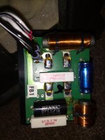
From the attached images it is difficult to see exactly what is going on in the area where the speaker wires are connected. Are the two black wires actually attached to the same piece of copper pcb track or is that just flux obscuring two individual pcb tracks. There does seem to be some solder splash at differing points that needs to be tidies up to prevent any shorts.
From the attached images it is difficult to see exactly what is going on in the area where the speaker wires are connected. Are the two black wires actually attached to the same piece of copper pcb track or is that just flux obscuring two individual pcb tracks. There does seem to be some solder splash at differing points that needs to be tidies up to prevent any shorts.
Attachments
Thanks Raymond
For what ever reason the image isn't opening so I'm downloading very very slowly??
I will pop the network and check once I can see the areas you pointed out and note the measurements.
As for solder splash I can confirm there is none, its all resin.
For what ever reason the image isn't opening so I'm downloading very very slowly??
I will pop the network and check once I can see the areas you pointed out and note the measurements.
As for solder splash I can confirm there is none, its all resin.
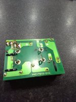
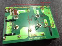
While you're trying to trace the schematic I've shown an example where I've flipped and rotated the other side so they are oriented the same. This is so you can mark the traces from the other side.
Also note that you can see the traces under the components, and you know the purpose of the external connections, but we don't.

Also note that you can see the traces under the components, and you know the purpose of the external connections, but we don't.
Hi Raymond
The values you listed are as I see it, As I recall did measure the resistors at the solder pads to make sure everything was connected. I can't measure caps and just used continuity across the inductors. The guy who drew the schematic gave some expected residence measurements for the whole pub which were spot on.
FYI the 56ohm resistor attaches from the through hole near where you wrote solder splash? and attaches top solder joint at the negative HF terminal effectively in parallel?
FYI the left image shows driver connections black cable LF white HF stripe is +.
from bottom to top LF- LF+ HF- HF+ on the right I've marked HF+ LF mimics positioning.
The values you listed are as I see it, As I recall did measure the resistors at the solder pads to make sure everything was connected. I can't measure caps and just used continuity across the inductors. The guy who drew the schematic gave some expected residence measurements for the whole pub which were spot on.
FYI the 56ohm resistor attaches from the through hole near where you wrote solder splash? and attaches top solder joint at the negative HF terminal effectively in parallel?
Hi Allen Thank you for doing that, I'm not sure I can flip images around like that so very useful.While you're trying to trace the schematic I've shown an example where I've flipped and rotated the other side so they are oriented the same. This is so you can mark the traces from the other side.
Also note that you can see the traces under the components, and you know the purpose of the external connections, but we don't.
View attachment 1009238
FYI the left image shows driver connections black cable LF white HF stripe is +.
from bottom to top LF- LF+ HF- HF+ on the right I've marked HF+ LF mimics positioning.
Download gimp.
And take a better photo of the back of the crossover, right in front of it and not lateral, as you did with the front. Using gimp you can reverse a photo and add text on it.
Ralf
And take a better photo of the back of the crossover, right in front of it and not lateral, as you did with the front. Using gimp you can reverse a photo and add text on it.
Ralf
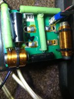
Do you have a later image of the completed boards as we cannot see where the 56 ohm resistor or the Solen 3.3 uf Capacitors are placed on your boards.
That may be where the subtle difference will be found, which may explain your findings on the current sound of your speaker.
Looking back at Fatmarley's useful link to the stereophile test results, especially the impedance shows that the original circuit schematic you posted with 6.8 ohm in parallel with the bass is a poor solution as it dampens the reflex LF peaks massively and causes quite a drop in response and will start getting hot quickly. When wired as a Zobel with the capacitor things become sensible again and it should match within component tolerances the Stereophile measured results.
I think the circuit when wired correctly and with correct driver phasing should allow you to tune probaly just using the 2.7 ohm ressitor value to tune by trying 3.3 -5.6ohm resistors is it still sounds to hot.
Currently you should have bass circuit with electrical 2nd order with your inductor and the 20uf and 6.8ohm zobel.
The tweeter is electrical 2nd order with 3.3uF with 0.91mH and 2.7 and 56 ohm forming an Lpad
Lets see images of what you have implemented.
Last edited:
Hi Raymond thank you for taking the time.
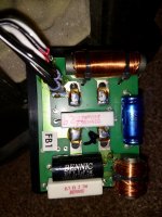
attached is one of the completed networks. It might not be the most elegant solution however I had to stay within the footprint of the enclosure opening. The solder legs have shine tube installed wherever they are in close proximity to another component and hot glued into place.
The 56ohm resistor is installed into the through hole to the edge of the board by the FB1 sticker soldered to the rear, and top soldered to a solder point hidden by the black cables. I followed the FB1+ layout and found a pic online from a random website but admit I didn't save the image
Attachments
I should mention something I found slightly odd, it could be my error I admit.
When checking the resistors today the 2.7 and 6.8 measured within tolerance 2.7 and 6.7 on both networks however, the 56ohms both measured 2.9 maybe something to do with the layout or my failure to measure correctly?
When checking the resistors today the 2.7 and 6.8 measured within tolerance 2.7 and 6.7 on both networks however, the 56ohms both measured 2.9 maybe something to do with the layout or my failure to measure correctly?
Which could suggest you have the 2.7 and 56 in parallel.
I still suspect you have one end of the 56ohm resistor connected incorrectly.
I still suspect you have one end of the 56ohm resistor connected incorrectly.
I won't say thats not possible however there is only 1 top solder position which is the - for the tweeter and whilst there are 3 holes at the other end 2 sit on an unused pad (visible from below, the other is the 3.3 cap. I used the one at the cap which correlates to the photo I found.
Hmmm,
It could also be looking back via the 2.7 ohm and the inductor say 0.3 ohm. It would be nice to see images of both sides to confirm. I know you say its a pain.
If simply you have done a good mod on the pcb it maybe you simply do not like the sound of the new tweeter.
If that is the case some more padding down of its level may help. You could try adding one of the old resistors you replaced to create more attenuation. I.e. two 2.7 ohm resistor's in series. Which should definitely reduce the treble a bit.
I have to admit I'm leaning towards the changes to the network and new tweeters simply being more revealing and less tolerant of recordings/positioning and room acoustics
Swapping the networks over seems to have balanced left to right slightly, maybe minor tolerance differences suit the other speaker/location etc a little better?
Having played various cd's now I can say its not an issue with all tracks even within the same cd right down to sections of tracks.
The speakers are too close together but I cannot change that.
Even sitting in one position and moving your head can alter the sound for better or worse, such is the small size of the "sweet" spot.
I've ordered a pair of XLR to RCA connectors which apparently bypasses an op-amp circuit in the dac. I may need to carry out a slight mod on pin connections to get the best from them.
If I can open up the sound stage it might help to balance things more.
I'm also curious if cleaning up or increasing capacity in the power supplies might help in that area?
Thank you for all your input, it amazes me the knowledge you guys have within the field.
- Home
- Loudspeakers
- Multi-Way
- Help with crossover?