Thanks. General information, but not taking a stand on the aspect in question. I'm seeing value in what markbakk has noted here (and my previous post).
The smaller the cabinet, the less troublesome standing waves inside it (they shift upwards). No back wave if dimensions are too small eh? (What is a back wave anyway).
What Mark is getting at is this: sound has to travel a certain amount of distance before it is a wave. It has to travel through at least one wavelength before it can behave as a wave. A resonance is possible at 1/2 wavelength, but this is not really "wave" behavior, it is more like a single degree of freedom resonance... analogous to a mass on a spring constrained to 1 dimension.
At frequencies less than 1 wavelength, your enclosure is basically a pressure vessel. it undergoes uniform pressurization and rarefaction cycles. If your largest box dimension is 8 inches, all sound below 1690 Hz is just pressure cycles.
At frequencies less than 1 wavelength, your enclosure is basically a pressure vessel. it undergoes uniform pressurization and rarefaction cycles. If your largest box dimension is 8 inches, all sound below 1690 Hz is just pressure cycles.
I'll keep that in mind next time I design a crossover. I don't understand the '3rd order acoustic' part yet, how can it be 3rd order if I only use one cap and one coil?
Your expectation is correct, that's exactly what happens.
OK a very important concept. I thought when I first looked at your slopes and phase that you had done it deliberately, but it seems it is just the way it worked out 😉
There are a number of parts to this puzzle. Your cap and coil form an electrical filter which will behave in a way that is dependent on the drivers impedance. If the impedance is completely resistive it should give a very constant roll off, and if you use say an online calculator it should be a perfect 2nd order roll off.
Now the driver not only has an impedance that varies with frequency, it also has it's own inherent roll off. The mid for instance will roll off on the low end below a certain frequency. Theoretically if in a sealed enclosure that will be at 12db / octave. So depending on where in the drivers bandwidth you are crossing over, the drivers natural roll off can also combine with the roll off that is provided by the electrical filter, which gives you a different roll off to what the electrical order of the filter would imply on it's own.
When I am doing a crossover sim, I add in target acoustic roll offs, and then tweak the crossover to get the actual roll off to match that acoustic target as closely as I can. Provided both drivers are within their operating range then you can get a quite symmetric contribution from each driver in the crossover range. This doesn't mean you can't do it asymmetrically, but I tend to like symmetry if it will work for particular drivers.
Tony.
That is a valuable remark. For mids in many designs, the fundamental resonance doesn't contribute a lot to the overall system output, certainly not when fc is quite low compared to the highpass function of the crossover. That doesn't mean you can ignore the resonance, electrically it will cause troubles with passive crossovers and acoustically badly damped resonances even at -20dB might be noticeable. Luckily most mids have high loss suspensions, the fundamental resonance will be quite low in most enclosures.The rear energy is a wanted part of the fundamental resonance over its extended bandwidth, why would you want to absorb it here?
However, standing waves in mid enclosures seem (to me) a much bigger challenge, as they mostly will appear in the passband of the mid. You obviously cannot damp them with the crossover like the fundamental resonance. So you have to revert to acoustical measures. That's where the absorbing materials come into play. And because you're using them in the resistive load frequency range of the driver, worries about the impedance of the absorbing material are quite unnessecary, even mineral fibers with densities up to 100kg/m3 will perform ok (where half that density will do just fine).
Btw close range measurements of mids reveal cavity resonances quite well, especially when converted into burst decay plots.
Last edited:
... Theoretically if in a sealed enclosure that will be at 12db / octave. So depending on where in the drivers bandwidth you are crossing over, the drivers natural roll off can also combine with the roll off that is provided by the electrical filter, which gives you a different roll off to what the electrical order of the filter would imply on its own.
Thanks for the clear explanation. However, I didn’t take any acoustical rolloff into consideration designing the crossover (natural driver rolloff nor cabinet induced). Only baffle step and diffraction (step having only a significant impact on the woofer, diffraction mostly on mid and tweeter).
To the other contributors: thanks for the insights around (mid) enclosure volume / damping etc.
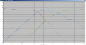
I've traced the original curves you posted, and loaded them into speakerworkshop and put in target slopes. My guesses were pretty damn close.
Red is a target slope for 3rd order butterworth at 600 Hz
cyan is 3rd order butterworth at 600 Hz on the hp section, and 2nd order bessel at 2.8Khz for the lp section.
yellow is 2nd order bessel at 2.8Khz for the tweeter.
So If I were doing this speaker I would be tweaking to get those lining up with the target curves, however my experience with bessel is that it is sometimes necessary to overlap the crossover point a bit, so say have LP target at 2.8Khz and HP at maybe 2.6Khz.
So hopefully that makes it more obvious what I am talking about 🙂 I'm quite surprised that you got such a close match to 3rd order butterworth on the woofer, if that was not actually what you were targeting! 🙂
Tony.
Attachments
I've been working on a design, and hope someone is willing to review it before I start ordering parts. There's a decent chance I got it wrong somewhere.
Design goals:
- Reasonably flat response
- Good low-end extension
- Within a modest budget
The last goal is because I know I'm still a novice at this. At this stage it would most likely be a waste to spend lots on premium drivers and crossover components.
For this project I'm thinking about creating a 3-way floorstander.
First I selected the drivers I want to use. For the bass I opted for the Dayton SD215A-88. A budget-friendly driver that doesn't need much volume in a BR enclosure. For mids I went with the Dayton RS125-8. I've used this driver before, and it sounds really nice to me. For the highs I choose for the Vifa/Peerless XT25BG60. It has a smooth FR and is acclaimed for it's price/performance. One driver of each per speaker (TMW). Any comments on these choices?
I calculated the volume needed for the bass driver using WinISD. I went with the default QB3 alignment, as the required volume works perfecty for me (though the BB4 and C4 alignments were not much different).
Next I designed a cabinet using Sketchup. I took the woofer magnet, bracing and BR volume into account to calculate the required woofer compartment (separated from the mid and tweeter).
Then I used VitiuxCad2 to trace the response graph of the Peerless tweeter and generate FRD and ZMA files (Dayton provides these files). I also used the 'Diffraction' tool to draw the baffle shape. For each driver I played with placement and generated an FRD file in which diffraction and baffle step are taken into account.
These ZMA and 'baffle compensated' FRD files were imported into XSim to design a crossover. I started off by following the instructions in the 'Introduction to designing crossovers without measurement' thread to calculate an LR2 network on each channel. Next I added L-pads to attenuate both the mid and the tweeter. To my surprise, things were looking quite promising at this point. I went on to tweak the values of components until I managed to get the FR graph within +/- 1dB between 100Hz and 20kHz. Next I made a shopping list of components, and adjusted values of the components in XSim to reflect those in the shopping list (like DCR for inductors and non-E12 values). The effect on the FR plot was very minimal. For cost and DCR reasons I went with an iron-cored inductor on the bass network. Would that be advisable in this situation? The crossover points are around 650Hz and 2900Hz.
At this point I could just go ahead with it and order all the parts. But I wonder if it would be better to just order the drivers first, build the cabinet, and measure the response of each driver unfiltered. Using the acquired data I could tweak the crossover further (or even start from scratch). But would this be worth it? Would you expect a lot of difference between real-world performance vs. simulations?
If measurement-based filter design would be recommended... I do have a Dayton iMM-6, an entry-level measurement mic. Don't know if it's fit for this purpose. Maybe I should invest in a UMIK-1? Or maybe even a Behringer ECM8000?
As mentioned earlier, it would be very much appreciated if a more experienced builder could review my design. I understand I'm asking a lot of questions.
I've learned most of what I know about designing and building speakers on the diyaudio.com forum. Youtube channels like 'Impulse Audio' and sites like audiojudgement.com also taught me a lot. But the more I learn about this stuff, the more I understand how much more there is to learn.
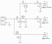
It is better to first have a crossover between low and mid/high, and then separate the mids and highs in a crossover behind that. Your diagram is basically wrong. Think about aligning phase shifts. Your tweeter needs to go to the same high pass section as the mid driver first, or the mid driver will have an additional phase shift that the tweeter does not encounter (as in your schematic).
Last edited:
So hopefully that makes it more obvious what I am talking about 🙂
It does, thanks!
I'm quite surprised that you got such a close match to 3rd order butterworth on the woofer, if that was not actually what you were targeting!
Beginners luck I guess. 🙂
@vacuphile, interesting, I've not actually seen that (that I remember) with passive three way schematics, but it is effectively what I have with my active cross for the low pass for the cross to woofer and high pass to then passive for mid and tweet.
I assume you mean to put the high pass for the mid first, then tap off after that for tweeter and finally the low pass for the mid. That should also have the benefit of reducing low frequency energy to the tweeter.
The sim should take into account the phase shifts no matter how it is wired, I'm trying to get my head around what is actually happening. The bandpass on the mid consisting of two second order filters should be in theory 360 deg and the phase shift on the tweeter only 180. If you do as you suggest, both would be getting 360 deg of phase shift? You would then not need to invert the mid (which in this case with the third order on the LP to the woofer, would not matter)?
Tony.
Phase shifts are calculated OK with about any network calculator. So one can check/compare both setups. To my experience, in a classic 3-way with a relative broad band mid the differences are negligible. But try, please try. Mind you, the same could be stated for the mid and the bass speaker, but I've seen no such setup yet.
It is better to first have a crossover between low and mid/high, and then separate the mids and highs in a crossover behind that. Your diagram is basically wrong. Think about aligning phase shifts. Your tweeter needs to go to the same high pass section as the mid driver first, or the mid driver will have an additional phase shift that the tweeter does not encounter (as in your schematic).
You mean the topology should be like this?
Attachments
Last edited:
I think so, you could also experiment with moving the lpad for the mid between the two sections (which would also require tuning of the tweeter lpad). But either way it is going to change the way the filters work and would require re-tuning them to get the desired response.
Tony.
Tony.
What Vacuphile says about filter interaction is good, but cascading filters is something I'd do with canned filters (for example digital).
Passive is versatile and freeform and you can achieve the result exactly by looking at the sim and meeting the requirements, whether you cascade or leave them parallel like before.
So what happens when you cascade the filters? While you can also achieve the exact result if you try, what you will have is interaction while designing. Every time you change one, the other will change as well.
That's a really good point Allen. I think it would also make it much harder to use an optimiser (like available in speaker workshop or vituixcad).
I downloaded the xsim file and had a play. I didn't need to invert the mid or tweeter so I'm not quite sure what the difference was with respect to phase (if any). I'm not really familiar with xsim so didn't look closely.
Tony.
I downloaded the xsim file and had a play. I didn't need to invert the mid or tweeter so I'm not quite sure what the difference was with respect to phase (if any). I'm not really familiar with xsim so didn't look closely.
Tony.
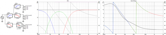
The issue in theory is that adding a second cross turns the mid into a bandpass. This modifies its phase compared to what it was with just the first cross. For the other driver in the first cross to meet this variation you need to add the influence of the second cross to it.
This image shows one common way to do it, and the original post leading to other ways it can be done.
(For those not familiar with VC, the filter type at the bottom right is an all-pass (phase only). It's passive equivalent is a lattice delay network.)
This image shows one common way to do it, and the original post leading to other ways it can be done.
(For those not familiar with VC, the filter type at the bottom right is an all-pass (phase only). It's passive equivalent is a lattice delay network.)
Attachments
... While you can also achieve the exact result if you try, what you will have is interaction while designing. Every time you change one, the other will change as well.
Then I'll just stick to separate paths for now, it's hard enough for me without them affecting each other. 🙂
Hi Tony,
I think you grasped it. The point I want to make is:
First crossover section should be between bass and mid/high.
From there, the mid section gets a low pass filter, and the tweeter gets a high pass filter. This ensures that the mid and the tweeter receive an identical phase shift as caused by the first crossover section. You can then design the filter between mid and high as you would with any normal two-way.
Then I'll just stick to separate paths for now, it's hard enough for me without them affecting each other. 🙂
Don't do it wrong because you think it will be easier, it is not. It is a lot more difficult to get it right after you made a fundamental error. Fortunately, the components stay the same, so it easy for you to experiment and find out for yourself. I assume you have a simple measuring microphone and a sound card? If you don't, making your own crossovers right is impossible anyways.
Why wouldn't the exact same be true for the bass and the mid? Phase sensitivity ends at about 2kHz (starting around 200Hz). That would mean for best phase behavior one better could add the lowpass of the woofer in series with the lowpass of the midrange, for most X-overs B to M are >200Hz and a lot of X-overs M to H are above 2k. Been through Linkwitz' writings, but this simple physiological aspect didn't get much attention there.
What Mark is getting at is this: sound has to travel a certain amount of distance before it is a wave. It has to travel through at least one wavelength before it can behave as a wave. A resonance is possible at 1/2 wavelength, but this is not really "wave" behavior, it is more like a single degree of freedom resonance... analogous to a mass on a spring constrained to 1 dimension.
At frequencies less than 1 wavelength, your enclosure is basically a pressure vessel. it undergoes uniform pressurization and rarefaction cycles. If your largest box dimension is 8 inches, all sound below 1690 Hz is just pressure cycles.
Returning to this topic, I wanted to first say thanks hifijim for this explanation that makes sense to someone without a science or physics or engineering background. I appreciate that.
Now what's not clear to me still is what the difference in behavior or effect is between the pressure cycles and a true wave if there is any. What seems to be implied is that the pressure wave is not attenuated with insulation. Perhaps also not reflected off the back panel. I'm not sure if it's being implied that transmission of the pressure wave through a medium is unaffected by the medium's physical properties. Or likewise if a panel or subpanel's resonance behavior is affected differently by the 2 different types of energy.
Perhaps I should start a new thread if this is deemed too far off topic.
- Home
- Loudspeakers
- Multi-Way
- Please review my design?