Just spotted, in a previous post, that the manufacturer's specification states "6W (ultra-linear connection)". So, it doesn't appear to be a SET. This means that there will almost certainly be a degree of overall negative feedback, and the exact output impedance will be difficult to ascertain - but it's likely that damping factor is quite acceptable.
In other words, don't worry about it! It's an amplifier - that's all.
$#@^&! 🙁
Thanks! Agreed, eyes totally 'glazed' over this too. 🙁
Regardless, vented yields the most LF extension even after vent damping [if required] and judging by the number of documented satisfied owners of tube driven reflex speakers Vs sealed in use around the world to this day makes me pretty confident it's going to continue to be the preferred default cab alignment. 😉
GM
I wanted (and still want) either Eminence Delta 12-A or Fane Sovereign 12-300 but.....I couldn't trace correctly the impedance curve for neither..... of them so I ended up with P.audio HP-12W and a Monacor d28n.....
OK, since my memory keeps screwing me over re tube systems, not sure what you mean by
Published spec-wise, the 12-A needs a Vb > Vas, Fb < Fs for flattest response whereas the 12-300 in theory works best overall with the pioneer's Vb = Vas/1.44 tuned to Fs, all measured specs of course for best results. 😉trace correctly the impedance curve
The HP-12W either sealed or some type of TL.
GM
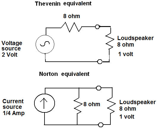
A more suitable relationship in the present case is V = E - Ir where V is the voltage available at the loudspeaker terminals, E is voltage developed by the amplifier and Ir is the voltage 'lost' across the internal resistance (r) of the amplifier. N.B. For internal resistance (r) we should really read output impedance (z) in the current discussion.I thought Ohm's Law was V= I x R as it goes.
From this relationship it is seen that the greater the current, I, drawn from the amplifier, the greater the 'lost volts' (Ir) and the smaller the voltage available to the loudspeaker.
In other words, if we ask the amplifier to deliver more current, the output voltage at its speaker terminals sags.
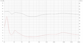
This is particularly of note with an SET amplifier of high output impedance when used with a loudspeaker which exhibits large variations in loudspeaker impedance with frequency.
When the impedance of the speaker goes low, the current increases and the voltage sags. The resulting SPL 'tracks' the impedance curve - dropping low when the speaker impedance drops low and rising high when the speaker impedance goes high.
The SPL is modulated as shown in the attached graph obtained courtesy of: Loudspeakers and Single Ended Tube Amplifiers - TestHiFi
So, as Steve correctly says, the ideal match woud be a loudspeaker with an overall flat impedance curve.
Attachments
That's correct, Keith. I blame Steve for using the term SET! 😀
The OP's amp is an SEUL (Single Ended Ultra Linear) pentode amplifier.
Ultra Linear Operation
However, does that alter the thrust of my argument in regard to output impedance?
The OP's amp is an SEUL (Single Ended Ultra Linear) pentode amplifier.
Ultra Linear Operation
However, does that alter the thrust of my argument in regard to output impedance?
However, does that alter the thrust of my argument in regard to output impedance?
No, but I did point out that an ultralinear output amplifier like this one would almost certainly have overall negative feedback, and therefore a low output impedance (lower than a ~1.5 ohm EL34 SET).
Then it occurred to me that the amplifier is relatively inexpensive, and that damping factor at bass frequencies might suffer, thanks to inexpensive output transformers. Hence it would perhaps be a good idea to measure output impedance - particularly if contemplating bass-reflex.
Thanks Keith. I'm glad to say I understood the opposing influences of NFB and poor transformer construction which you mentioned in your original posts.
I guess it is unlikely that we'll discover the magnitude of the output impedance of the OP's amplifier.
Sealed or vented? Looks like there's no definitive answer in this case.
I guess it is unlikely that we'll discover the magnitude of the output impedance of the OP's amplifier.
Sealed or vented? Looks like there's no definitive answer in this case.
Nobody is arguing here about the benefits of reflex bass loading in terms of getting an extra octave of bass.
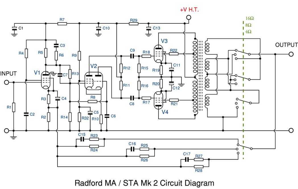
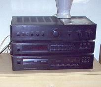
But what we are talking about is Valve amplifiers. I inherited this astonishing Radford STA-25 amp. Goes for big bucks on eBay.
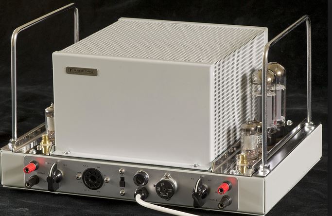
Very different animals from your more usual Rotel Voltage Feedback jobbies:
Honestly, price no object, give me valves any day:
Stereo 40 MkIV Integrated KT88 Amplifier - Stereo 40 MkIV - Integrated Amplifiers
But they need some thought to work well.
But what we are talking about is Valve amplifiers. I inherited this astonishing Radford STA-25 amp. Goes for big bucks on eBay.
Very different animals from your more usual Rotel Voltage Feedback jobbies:
Honestly, price no object, give me valves any day:
Stereo 40 MkIV Integrated KT88 Amplifier - Stereo 40 MkIV - Integrated Amplifiers
But they need some thought to work well.
For measuring the output impedance of an amplifier, I use the "Half Voltage" method emplyed to determine internal resistance of a generator :
U = E-Ri
U = voltage at the poles of the generator
E = no-load voltage at the poles of the generator (i = 0)
i = current delivered by the generator
R = internal resistance or impedance of the generator
You need a variable resistor (say 0-10R), an audio generator set at say 400Hz, a DMM in VAC.
1 - Measure your amp voltage output without load. Manage to set your audio genrator at low level, in order to obtain circa 5 to 8VAC max without load. This is E.
2 - Connect your variable resistor at the amp output and set it to read half of the no-load voltage E. This is U.
3 - Disconnect the variable resistor and measure its value. This is R, the internal ressistance or impedance of your amplifier.
For example, on my project of SE amp using a KT88 in UL operation, with 10dB NFB, I measure an impedance of 2.5R by this method. For my U-300B which has no NFB, I measure 4.3R. This give you an idea of what you can expect...
A+!
Hello All,
My solution:
Connect up the tube amplifier, an inline current sensing 0.1R resistor and connect it to your analyzer.
Run an impedance plot, a phase plot and whatever other tests you want.
Adjust the ports and damping to your liking.
Or test the speaker in a sealed enclosure.
Pick the plots that you like and run it that way for awhile and see how you like the way it sounds to your ear.
Thanks DT
This all reminds me of my introduction to Floyd Toole: http://www.roger-russell.com/wire/damptoole.htm
GM
GM
Thank you all for the time and the effort you all put in answering my question. It's been an interesting journey so far. Please, don't stop, it's a long learning process from my part.

This all reminds me of my introduction to Floyd Toole: http://www.roger-russell.com/wire/damptoole.htm
GM
If you read Dr. Toole article the first paragraph tells us that Dampening Factor is defined only using resistance and that Damping Factor does not matter so much as to be important. With that being said you need not read any more of the article about Damping Factor.
Output impedance is much more important of a concept than DF. Output impedance often is an indirect measure of amplifier negative feedback. The speaker input terminals connect to the amplifier output terminals. Negative Feedback is a loop that also connects to the amplifier output terminals. The Feed Back loops back to an earlier inverting stage of the amplifier.
The speaker has stored energy or pendulum like effect. Once it starts to move it continues to move even without additional input. As the speaker continues to move at its’ resonant frequency the voice coil moves through the speaker magnetic field and generates a voltage called Back EMF. By way of NFB the amplifier actively damps the resonant ringing of the speaker.
This is not Dr. Toole’s Damping Factor.
Old school tube amplifiers have zero or minimal amounts of NFB.
Thanks DT
Damping factor is an indirect measure of output impedance and is a term mainly intended for the layman.
It's more easy for the average punter to understand that a high damping factor gives better control of the loudspeaker.
Of course, output impedance is the correct measure as it remains the same regardless of the impedance of the speaker load.
If an amplifier has an output impedance of 1 and it drives an 8 ohm loudspeaker then the damping factor (Zls/Zout) is 8.
Connect a 4 ohm loudspeaker and the damping factor becomes 4, suggesting damping has decreased, when in fact output impedance remains the same.
Going back to the OP's original question, a single ended amplifier with no feedback and little bass control should be matched with a well damped loudspeaker.
If the speaker used is heavily acoustically damped, it requires little electrical damping and that's where the positive factors of an SE amp, like low level linearity, come to the fore.
Most speakers are a little under damped acoustically because they will have been driven during the design process by a transistor amplifier with its high electrical damping.
Correction: 'If an amplifier has an ouput impedance of 1 ohm...'If an amplifier has an output impedance of 1 and it drives an 8 ohm loudspeaker then the damping factor (Zls/Zout) is 8.
There is a subtlety in words like these. I'm not saying it's you. Certainly there are others I've noticed reading something extra into this.a single ended amplifier with no feedback and little bass control should be matched with a well damped loudspeaker.
If Zo interacts with the speaker impedance, and the response changes, and you then equalise that back at a point before the amplifier, then you are going to produce the same end result as a Voltage amp would give.. response, phase and ringing.
Perhaps I'm suggesting that any variation in control is specific and repeatable, as well as reversible according to filter theory. This does not imply the same thing as, for eg suggesting 'loss of control'.
Not so fast. Is the ringing produced by the reactive nature of a driver which has a limited bandwidth? From a crossover component interacting with the impedance? From a driver resonance? Can it be measured as a response variation?
Did you read the link above in post #51?
EQ might be a good thing.
Did you read the link above in post #51?
EQ might be a good thing.
- Home
- Loudspeakers
- Multi-Way
- Sealed or vented