For this loudspeaker under
Wilson Audio Specialties, Inc.
Wilson Audio WATT/Puppy System 5 loudspeaker Watt/Puppy 5.1 upgrade | Stereophile.com
https://www.wilsonaudio.com/pdf/manuals/manual-watt-puppy-series-5.pdf
I want to realize a bi-amping preparing. Therefore I need the schematic of the crossover network.
I hope, that the crossover network isn't a potted version like in version 8 - go to fifth picture under
SoundStage! Equipment Feature Review - Wilson Audio Specialties WATT/Puppy 8 Loudspeakers (3/2007)
Thank you for an upload.
Last edited:
much seems to be secret with wilson audio, and they call things for mysterious names. I do not think that xo is worth so much to copy, I have to look hard to find a loudspeaker with more remarkable frequency response, sometimes i wonder if they knew at all what they where doing on the earlier models, later models are designed with a completely different knowledge
maybe you can ask at wilson audio forum over at what's best forum
Wilson Audio Speaker Forum | What's Best Audio and Video Forum. The Best High End Audio Forum on the planet!
oh, i love those old websites, like the wilson, thanks for the link
maybe you can ask at wilson audio forum over at what's best forum
Wilson Audio Speaker Forum | What's Best Audio and Video Forum. The Best High End Audio Forum on the planet!
oh, i love those old websites, like the wilson, thanks for the link
I own the 7 and the crossover is not only split in two, but the Puppy part also includes a 200uF cap leading to the Watt cross. I guess they did it this way just to dissuade users from bi-wiring or bi-amping easily ")
Should you decide to unpot i'd be very curious to see all the crappy parts they are hiding under that epoxy
Should you decide to unpot i'd be very curious to see all the crappy parts they are hiding under that epoxy
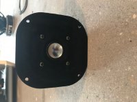
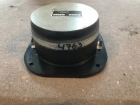
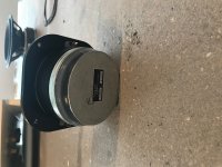
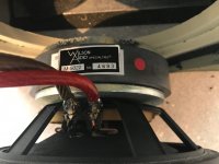
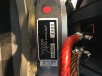
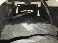
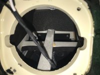
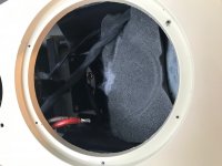
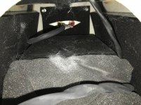
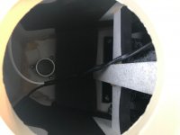
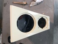
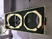
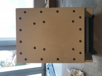
the biggest difficulty is the fact that the pottet crossovers are still stuck firmly to the walls of enclosure resp. envelope. Thus a measuring procedure without and with crossover network will provide the part values (µF/mH) by compare with external components. Now some pictures of the transducers and cabinet:I own the 7 and the crossover is not only split in two, but the Puppy part also includes a 200uF cap leading to the Watt cross. I guess they did it this way just to dissuade users from bi-wiring or bi-amping easily
Should you decide to unpot i'd be very curious to see all the crappy parts they are hiding under that epoxy
Attachments
-
 Focal-Wilson Audio T-5012 front.jpg614.3 KB · Views: 1,483
 -
 Focal-Wilson Audio T-5012 rear-I.jpg702.6 KB · Views: 1,417
 -
 Focal-Wilson Audio T-5012 rear-II.jpg669.6 KB · Views: 1,782
 -
 Focal-Wilson Audio T-5012 rear-III.jpg701.1 KB · Views: 1,366
 -
 Scan-Speak Wilson Audio M-5022 rear-III.jpg480.2 KB · Views: 946
 -
 Scan-Speak Wilson Audio M-5022 rear-II.jpg552.6 KB · Views: 981
 -
 Scan-Speak Wilson Audio M-5022 rear-I.jpg575.4 KB · Views: 1,316
 -
 Scan-Speak Wilson Audio M-5022 front.jpg753.2 KB · Views: 1,409
 -
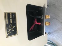 Wilson Audio Puppy Terminal-II.jpg407.2 KB · Views: 917
 -
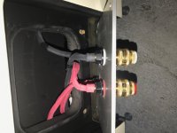 Wilson Audio Puppy Terminal-I.jpg531.2 KB · Views: 912
who can replace the suspension of Wilson's custom made T120 version ?
Attachments
-
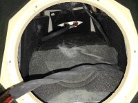 Wilson Audio Watt Envelope-X.jpg913.6 KB · Views: 768
 -
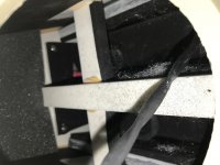 Wilson Audio Watt Envelope-VIII.jpg505.7 KB · Views: 585
 -
 Wilson Audio Watt Envelope-VII.jpg514.6 KB · Views: 573
 -
 Wilson Audio Watt Envelope-VI.jpg523.6 KB · Views: 549
 -
 Wilson Audio Watt Envelope-V.jpg602.4 KB · Views: 565
 -
 Wilson Audio Watt Envelope-IX.jpg520.9 KB · Views: 585
 -
 Wilson Audio Watt Envelope-IV.jpg407.4 KB · Views: 589
 -
 Wilson Audio Watt Envelope-II.jpg591.4 KB · Views: 657
 -
 Wilson Audio Watt Envelope-I.jpg766.8 KB · Views: 672
 -
 Wilson Audio Puppy bottom view.jpg398.5 KB · Views: 611
I have played a bit with variuos watt puppies and also measured looked a bit inside sasha WP1. those speakers really suffers from lower midrange absence, midrange rolls of very early and bass does not cover that range either. very few rooms can acomodate it
try this trick- use 2.7-3.3mh 0.15ohm iron core inductor after 200uf cap. impedance will dip to 1.5-2ohms but you will have increased lower mids. then just feed bass woofers separately. only biamping will not help you as you get large bump at 100hz and weak 200-400hz.. good luck
try this trick- use 2.7-3.3mh 0.15ohm iron core inductor after 200uf cap. impedance will dip to 1.5-2ohms but you will have increased lower mids. then just feed bass woofers separately. only biamping will not help you as you get large bump at 100hz and weak 200-400hz.. good luck
You don't need the original schematic to duplicate the transfer function.
Measure the electrical frequency response at the drivers. Just keep your output low enough and you can use REW to measure this directly.
As others have written however, that may not be what you want.
I'd rather take on a brand new kit from Troels or a 2.5 way with a Revelator tweeter and woofers.
Best,
E
Last edited by a moderator:
Wilson guards their schematics like a vault filled with gold ! I have a pair of Watt 3 Im playing with and they are not easy unless the tweeter, which is a watt 5 version is really tamed with some L pad . I dont have the puppy but have tested a simple 2nd order low pass to a first order high pass at around 120 hz with great success on a sub box I Built with twin 8 drivers ... It dont seem to tax the amp ! I have 4 new drivers coming next week that SIM almost identical to the Dynaudio 21w54
That tweeter motor had a NON replaceable coil. The later TC 120 has a removable pack like Scan speak. I had to ruin a set of T120Ti to make mine work .. Do you have blown tweeters ?
That tweeter motor had a NON replaceable coil. The later TC 120 has a removable pack like Scan speak. I had to ruin a set of T120Ti to make mine work .. Do you have blown tweeters ?
Last edited:
Good morning,
does anyone have the crossover schematic of the WATT5? I am not using the Focal tweeter but instead l wanna try the Scan Speak D2905. I need it for the 18W/8545-01. I already tried a few circuits with a 12db slope, but I am sure to get a better result. l use for example 1 R/C with 10ohms and 10 uF.
Thanks in advance,
Barolo
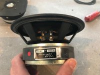
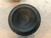
the biggest difficulty is the fact that the pottet crossovers are still stuck firmly to the walls of enclosure resp. envelope. Thus a measuring procedure without and with crossover network will provide the part values (µF/mH) by compare with external components. Now some pictures of the transducers and cabinet:
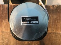
Nice relabeling of these drivers,
I always find it super silly to be so fancy about a crossover schematic.
Just reverse engineering usually doesn't take that long.
Just a matter of visual inspection in combination with measuring some parts.
It's not really rocket science.
what are you trying to do? NO one has Wilson schematics unless you have opened a potted x over and measured each component ! I cant confirm nor deny that I have ! I know this .. Unless you want to spend some money on caps and coils and have good x over skills leave it to someone who does. The Watt was designed to be a Monitor. As the iterations went up they became more audiophile. Each one getting better control of that tweeter . When a Focal is done right its magic! I have several of them and built many designs with them !
There are many great two way designs using the 8545 and scan tweeters !
There are many great two way designs using the 8545 and scan tweeters !
what are you trying to do?
NO one has Wilson schematics unless you have opened a potted x over and measured each component ! I cant confirm nor deny that I have ! I know this .. Unless you want to spend some money on caps and coils and have good x over skills leave it to someone who does. The Watt was designed to be a Monitor. As the iterations went up they became more audiophile. Each one getting better control of that tweeter . When a Focal is done right its magic! I have several of them and built many designs with them !
There are many great two way designs using the 8545 and scan tweeters !
Didn't I mention that in post #1 ?
Hello,
l owe a Wilson clone of the WATT3, made by a german guy 1997 who bought a pair of WATT3 without the PUPPY and opened it. He was actually a little bit disappointed how simple the x over was designed. He made a few copies of it and sild them under the name ´´Progressive Audio Diablo´´, later also with a scan speak 8545. On my clone I changed the x over a bit, because the speaker sounded a bit ´´griddle´´, what ever that means. In German we would call it ´´´out of a pot.
l owe a Wilson clone of the WATT3, made by a german guy 1997 who bought a pair of WATT3 without the PUPPY and opened it. He was actually a little bit disappointed how simple the x over was designed. He made a few copies of it and sild them under the name ´´Progressive Audio Diablo´´, later also with a scan speak 8545. On my clone I changed the x over a bit, because the speaker sounded a bit ´´griddle´´, what ever that means. In German we would call it ´´´out of a pot.
I'm sure that there is a formal way of determining what's inside a crossover black box.
2 port network analysis.
But here is a probably good enough way:
I'd use an accurate ohm meter to first determine if the ground is straight through,
then the R in to out, in to ground, out to ground to determine the DCR of any inductors.
Then load the network with an 8 ohm 1% resistor and measure the frequency response.
Look at the slopes and passband attenuation for a first guess at the network. Then iterate
in Xsim (also loaded with 8 ohms) to duplicate the transfer function. Measuring the input
impedance just as another check and comparing to the sim will help verify the result.
You can do other things such as shorting the output and measuring the input impedance
again, shorting the input and measuring looking back from the output, etc.
I've done this with speakers that had glued in crossovers.
I think that Don Keele in his excellent Audio review listed the number of components in
the crossover - its been a long time I should reread it page 54 in the .pdf:
https://worldradiohistory.com/Archive-All-Audio/Archive-Audio/90s/Audio-1996-02.pdf
I'd really like to see the schematic!
Last edited:
Might be some hints here in Fig. 7:
Wilson Audio WATT/Puppy System 5 loudspeaker Measurements part 2 | Stereophile.com
Wilson Audio WATT/Puppy System 5 loudspeaker Measurements part 2 | Stereophile.com
- Home
- Loudspeakers
- Multi-Way
- Schematic of potted crossover network for Wilson's Watt V/Puppy V.1 wanted