_ That quote kind of lends a clue. The peaks we see in the electrical impedance as a result of resonance....how to gauge the effect as opposed to the reading of the chart. Maybe I should say, how in or out of control the driver is, as opposed how high/low the graph reads. Resonance can mean higher decay times, and maybe higher xmax at times? Not sure. I'm going to stick with lower is better but I can't say that I know what medium is or low or super high/low....I think that 20ohms is decently low if not abnormally... probably the type of impedance response I'd get with some type of aperiodic port thingy....combined with a tuned truncated back-horn...Loudspeakers can be designed to exhibit almost constant impedance,
although it is rarely done. Su loudspeakers can perform with remarkable
consistency
Last edited:
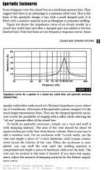
Aperiodic Loudspeaker Enclosure Design
Aperiodic Enclosures - Great Sound Stereo Speaker Manual
Finally some type of comments geared towards my inquiry but I don't feel like I'm confidently educated on the topic just based off of this reading. Am I tapping into outdated ideology... or is there something to gain with a flattened impedance and to how low is low enough???
Enthusiasts of aperiodic enclosures will often compare the performance with transmission line enclosures, in that the design avoids "ringing" effects of ported enclosures, while alleviating the "pressure effect" of a sealed box.
This results in clearer, better defined bass, with more amplifier power and control into the lower frequencies.
Aperiodic Enclosures - Great Sound Stereo Speaker Manual
Some speaker authorities make much of a flattened impedance curve; others say its irrelevant. Advocates of the aperiodic enclosure system compare it to the much larger transmission lines. They say the damped aperiodic enclosure avoids the possibility of ringing with a reflex while relieving the "oil can" pressure effect of the closed box
Finally some type of comments geared towards my inquiry but I don't feel like I'm confidently educated on the topic just based off of this reading. Am I tapping into outdated ideology... or is there something to gain with a flattened impedance and to how low is low enough???
Attachments
Flattened impedance is a significant benefit when doing a passive crossover because it will affect the filter response but less important with active filters and xo. The primary figure of merit for a loudspeaker is its frequency response and you will see nary a ripple in the FR of a sim at the impedance peak. However, the impedance and the peaks and ripples in it are symptomatic of other things; in your case the adequacy of the TL damping - but you can also see that and more directly in the FR.
I would make an effort to understand the causes of the various peaks and ripples in an impedance measurement and to smooth them out, but I wouldn't look for the Z to be above or below any particular number, except to be high enough as to not be problematic for the amplifier.
I would make an effort to understand the causes of the various peaks and ripples in an impedance measurement and to smooth them out, but I wouldn't look for the Z to be above or below any particular number, except to be high enough as to not be problematic for the amplifier.
However, the impedance and the peaks and ripples in it are symptomatic of other things; in your case the adequacy of the TL damping
My thoughts as well. They usually are a reflection of a resonance, the electrical impedance is a reflection of what is going to happen on the mechanical level, and thus some type of affect on the sound produced. I think ringing is the big deal? Ringing/Decay..... but how to relate a level of decay vs what is reflected in the impedance.....If loudness is properly achieved, the more dampening the better is the best thing I can come up with....I can't see an instance where you would want a system to resonate any more than is necessary. So dampen all the way until right before it becomes too much, too much being when the dampening starts to create power issues for the driver and loudness goals.... I dampened until the excursion vs input vs output made sense. I put xmax at 777watts at 115db. I also compared this to sealed and ported...Ported has higher efficiency and Sealed has lower.
This is the chapter about impedance versus amplifiers (damping factor) versus loudspeaker cable.
Yes, before opening a large can of worms there should be some prerequisite readings before stimulating discussions
") .
.Continuing with the horns from post Is it possible to cover the whole spectrum, high spl, low distortion with a 2-way?
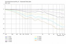
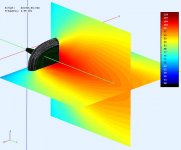
These are the sim results for the "dxc464_01" as a compromise that does not go as low in return for a smaller horn. The round over (with a flat backside) has been added to the original horn profile.
P.S. Sorry, they are a little late. I found a issue with certain models and spent a few days experimenting with ABEC to identify it and fix it.
.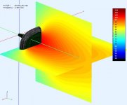
Attachments
Last edited:
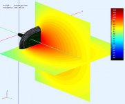
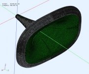
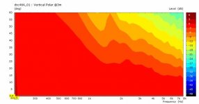
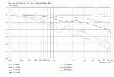
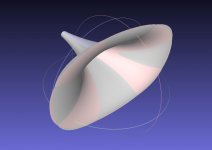
Also interesting is @docali provided another version "dxc464_02" of this same horn profile with a more elliptical mouth. The two horns are overlaid (pic#1) to show how similar the profiles are. The "pinkish" parts are the dxc464_02 showing through near the mouth.
A roundover has been added as well and the performance of the two horns are very similar.
.
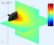
A roundover has been added as well and the performance of the two horns are very similar.
.
Attachments
-
 OverLay_DXC454_V1+V2.jpg51.3 KB · Views: 77
 -
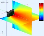
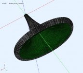 dxc464_02-3dView.jpg67.5 KB · Views: 78
 -
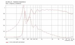
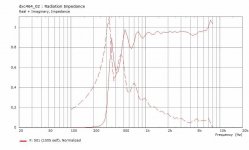 dxc464_02-RadImp.jpg38.1 KB · Views: 73
 -
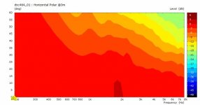
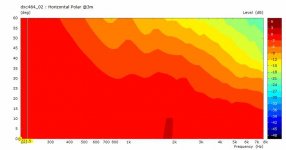 dxc464_02-HorzPolar@3m.jpg23.1 KB · Views: 67
 -
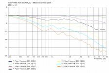 dxc464_02-HorzPolarCurves@3m.jpg43.7 KB · Views: 55
 -
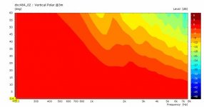 dxc464_02-VertPolar.jpg24.5 KB · Views: 58
 -
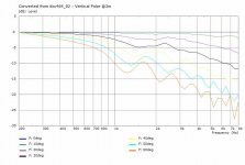 dxc464_02-VertPolarCurve@3m.jpg39.9 KB · Views: 52
Hi Don!
Very interesting results! Thanks! It seems that the round over minimizes the differences between rectangular and elliptical. The last sim show a sudden increase for the impedance. I would assume tat this is an artifact of the mesh size? The two horns are very similar and I would not understand this difference.
Very interesting results! Thanks! It seems that the round over minimizes the differences between rectangular and elliptical. The last sim show a sudden increase for the impedance. I would assume tat this is an artifact of the mesh size? The two horns are very similar and I would not understand this difference.
Hi Don!
Very interesting results! Thanks! It seems that the round over minimizes the differences between rectangular and elliptical. The last sim show a sudden increase for the impedance. I would assume tat this is an artifact of the mesh size? The two horns are very similar and I would not understand this difference.
dear both, Id like to see what you find with this as I have a 4594HE to use in my 15in setup!
Im actively looking for a horn from 650ish and up. Like this one. (home use, no high spl)
Can anyone post some impedance curves of subwoofers that they would call the holy grail of bass sound quality?
Hello camplo
Curious, what are you looking for in the curves? Symmetry of the peaks for a reflex enclosure? Magnitude of the peaks? Both? Something else?
Rob
Can anyone post some impedance curves of subwoofers that they would call the holy grail of bass sound quality?
A point source driver? From an impedance POV the one with the lowest inductance, flattest impedance over the widest BW. Otherwise, look to servo sub driver designs for best of the best with horn loaded being the current pinnacle TTBOMK [no experience with fan designs].
GM
I can totally see on paper how a transmission line has the best bass according to many accounts on this board. I'm currently googling brand name studio monitor subwoofers impedance curves but haven't found much. I don't know what models of subwoofer the crowd here considers to be "remarkable". Name some, or drop some "impressive" subwoofer impedance charts.
Check-Out This Website ....
dB v2
if you have not already do so.
WHG
Can anyone post some impedance curves of subwoofers that they would call the holy grail of bass sound quality?
dB v2
if you have not already do so.
WHG
Thanks whgeiger! Can you guy guys see what I am doing? I just need to see whats possible and wants being considered high SQ. As GM stated "the one with the lowest inductance, flattest impedance over the widest BW" ....well have you seen the modeled impedance of the enclosure I designed? It would be nice to know the power compression specs of my woofers so that I can make a judgement on system efficiency vs potential power compression but 777watts is the desired max volume at 115db, so 110db is around 300watts and thats at half space and only one of two. The RMS is 1000watts... I don't think power compression is going to be an issue, considering even common lower playback volume like 100db divided between the two subs. I wonder if AE will share the power compression specs.
I feel like I'm missing one thing....rigidity of the woofer cone....is this even a measurement?, how much dampening from the line can the cone take?
ON the other hand, judging by the output of the driver only output of the TL, I'm not clamping down hard like one might think, more so, the output and resonance is decreasing more so because of less resonance of the Line, due to less efficiency of the line.
ON the other hand, judging by the output of the driver only output of the TL, I'm not clamping down hard like one might think, more so, the output and resonance is decreasing more so because of less resonance of the Line, due to less efficiency of the line.
Last edited:
- Home
- Loudspeakers
- Multi-Way
- Is it possible to cover the whole spectrum, high SPL, low distortion with a 2-way?